


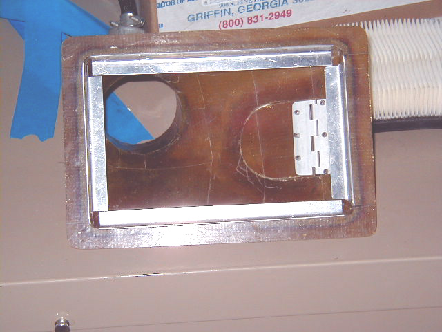

The following series of photos details the creation of an airfilter mount for the air induction system shaped from foam and glassed with 3 layers BID then mounted. The final several photos show installation of a spring-loaded alternate air intake door in the mount. If the filter becomes clogged for any reason (eg., ice), the door would swing open to allow continued air flow to the engine.
Click on thumbnails to view larger versions of the pics!
|
|
|
|
|
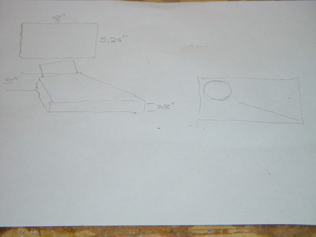
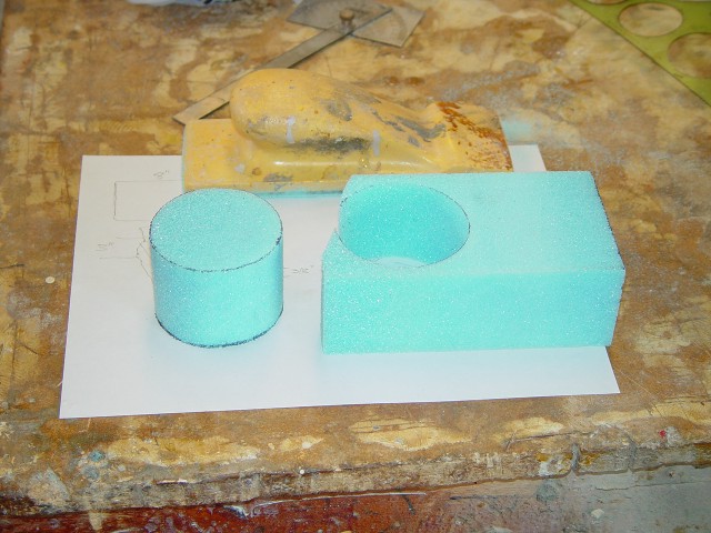
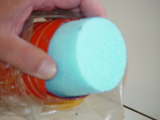
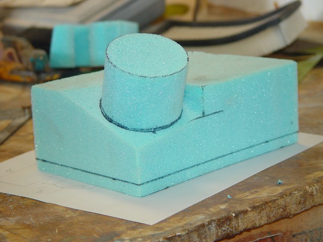
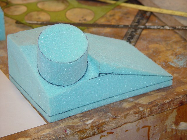
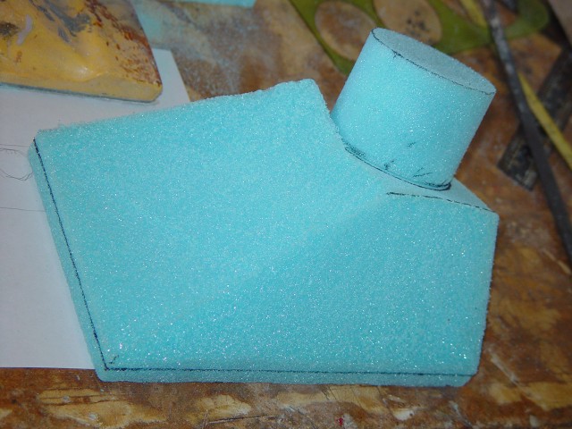
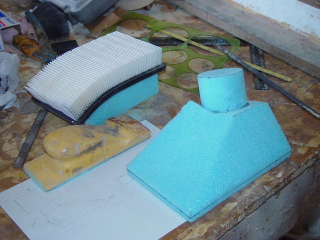
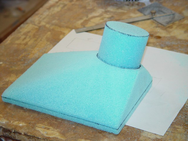
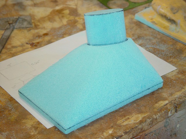
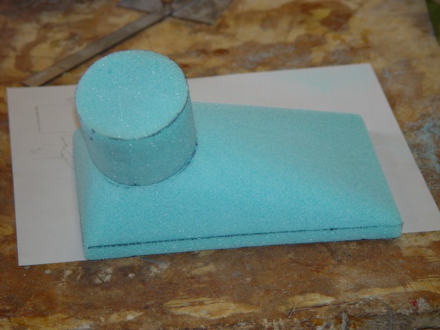
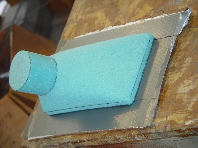
| Diagram showing dimensions of mount to be fabricated. Size dictated by size of air filter seen in following photos. | Band saw used to cut out a circular piece of foam to make connector to tubing. | Foam circle sized to allow for fiberglass layup on outside. | Circular piece glued to foam block roughly shaped to appropriate dimensions. The following photos show how the block is shaped step by step with a hacksaw blade and sanding block. |
|
|
|
|
|
|
|
|
|
|
|
|
|
|
|
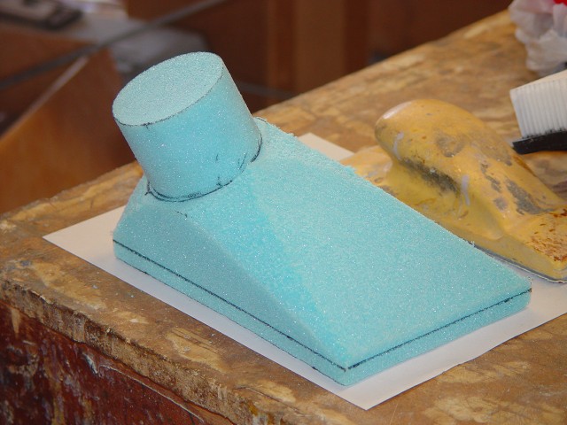
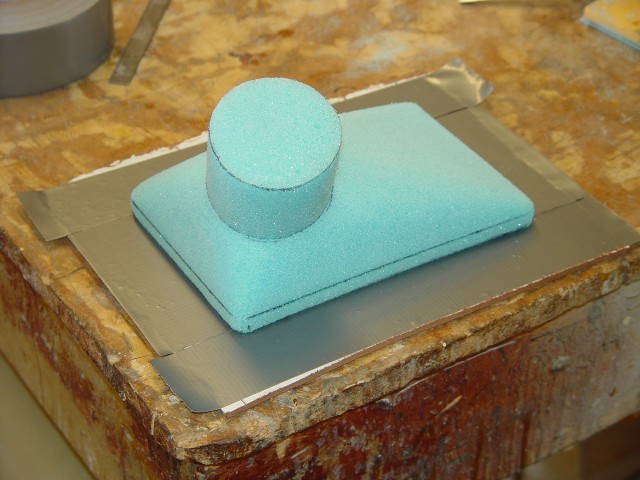
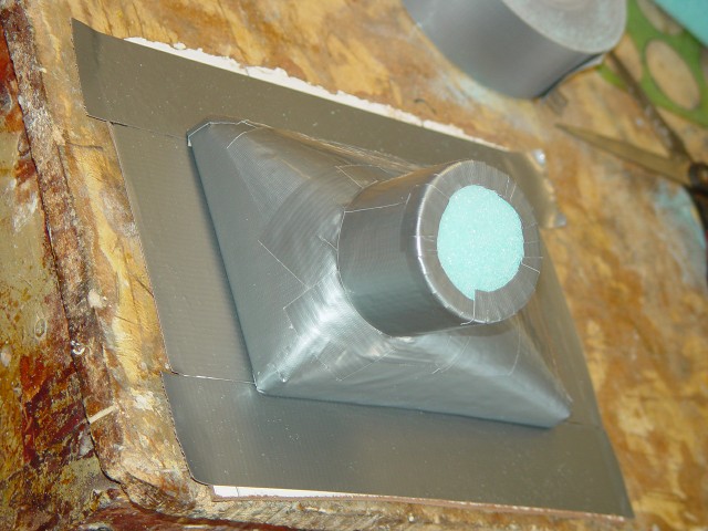
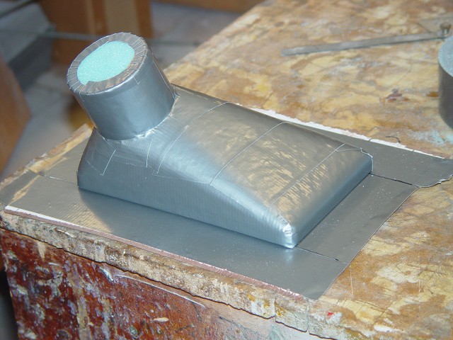
| Final shape foam block mounted on piece of formica covered with duct tape to for flat flange. | Foam part covered with duct tape in preparation for glassing. | ||
|
|
|
|
|
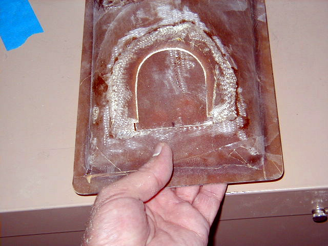
| Part ready for glassing propped in position on top of wing root in rough orientation that is will be installed. You can see the cavity in the wing root in lower center of photo over which the mount will be placed. | Air filter mount glassed with 3 layers BID. | ||
|
|
|
|
|
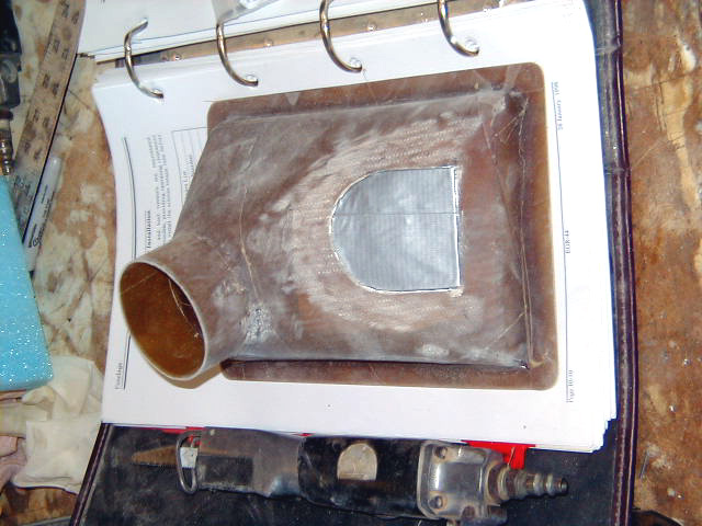
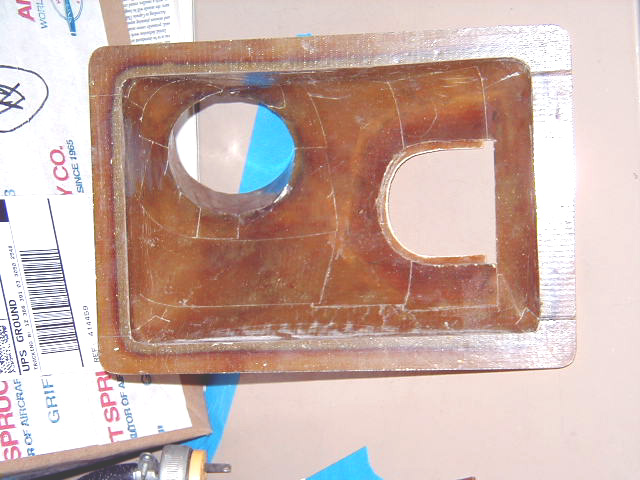
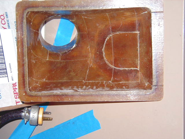
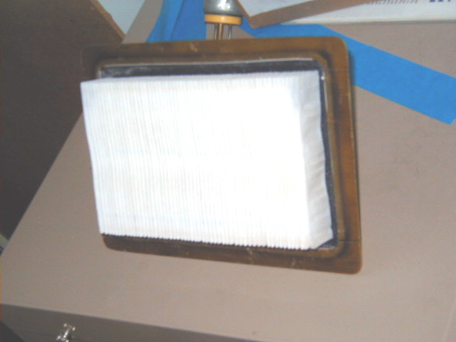
| Filter mount cured and flange to be trimmed. Foam dissolved as seen in the fabrication of the NACA scoop slip joints. | Inside view of filter mount. | ||
|
|
|
|
|
|
|
|
||
 Comments, questions, and suggestions are welcome! email: rich@rguerra.com
This page visited times.