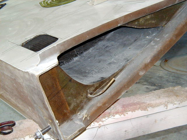
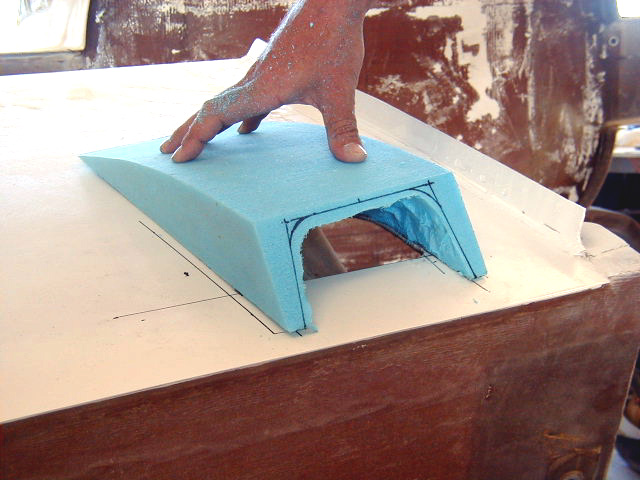
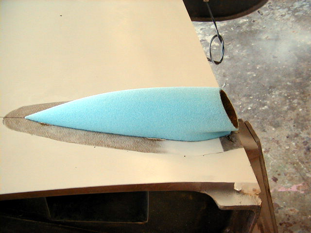


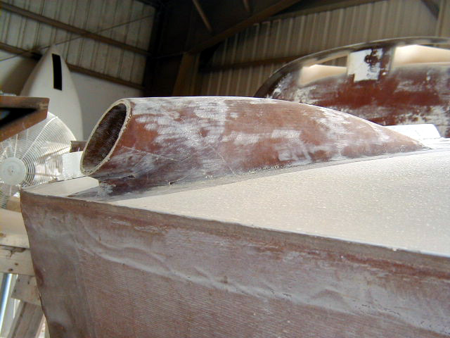
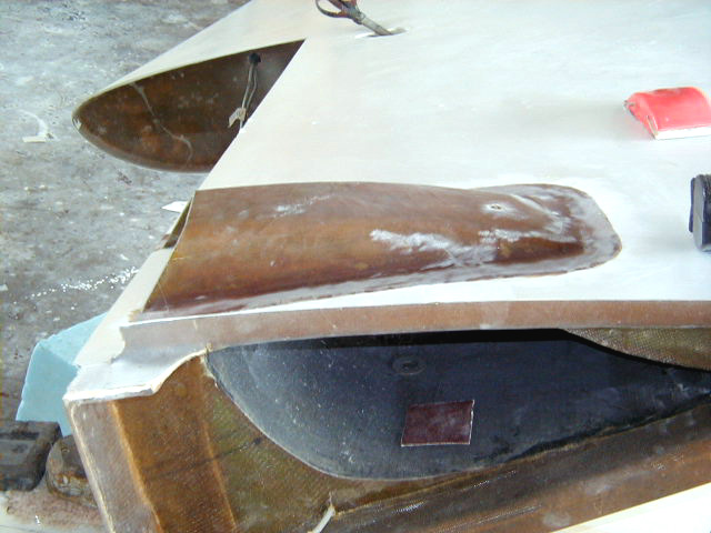


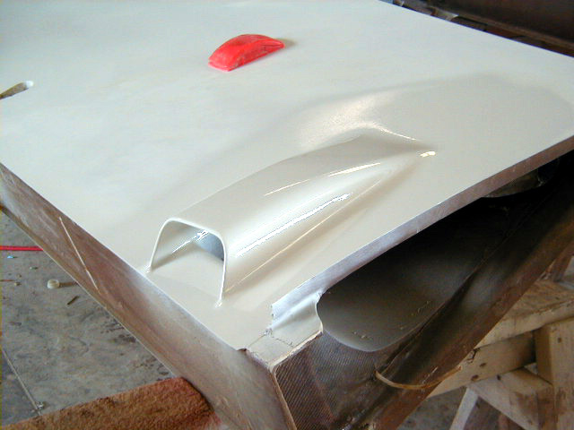
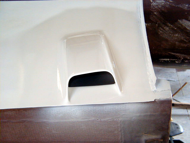


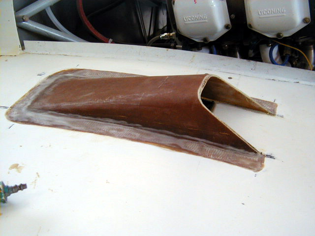


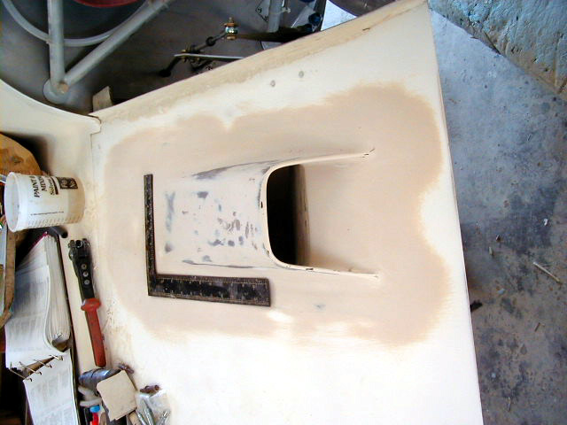
Construction details of Induction System and wingroot Oil Cooler inlet scoops and Oil cooler outlet. The Oil Cooler inlet is located on the undersurface of the pilot side wing; the Induction Air inlet is located undersurface of the copilot wing. They were formed by shaping and then glassing over blue foam as shown below.
2015 cheap best swiss rolex,panerai,iwc,hublot,tag heuer,breitling,patek philippe,omega Constellation watches,omega DeVille watches,omega Seamaster replica,top quality bvlgari,cartier,chopard,corum,franck muller,longines,tissot,u-boat,ulysse nardin,versace,glashutte,graham jaeger lecoutre.we also keep these watches entire brands:audemars piguet,breguet.
|
|
|
|
|
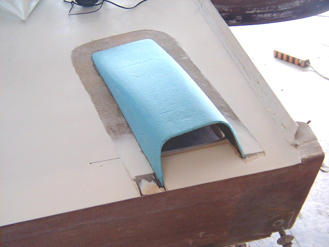
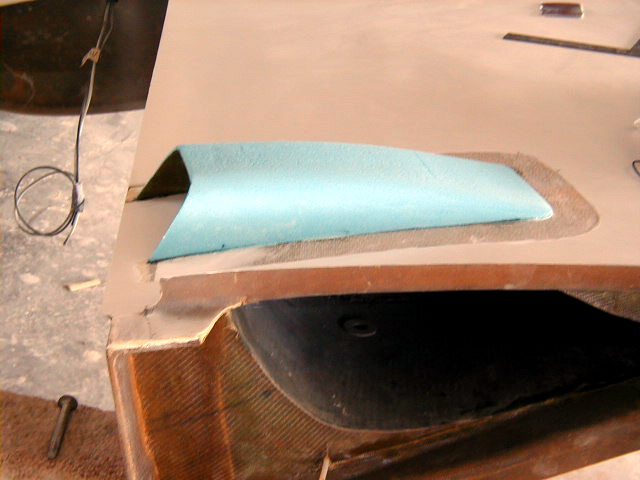
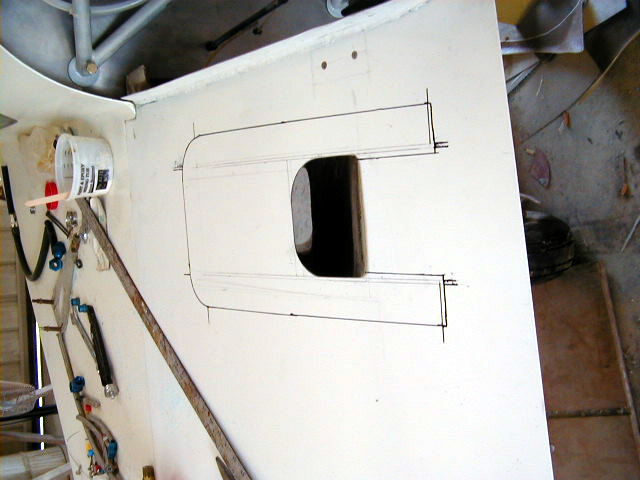
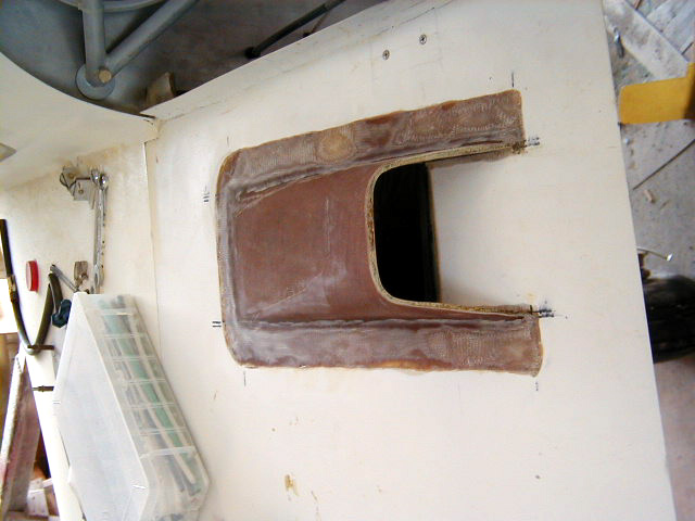
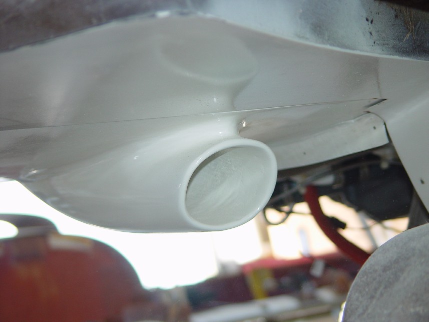
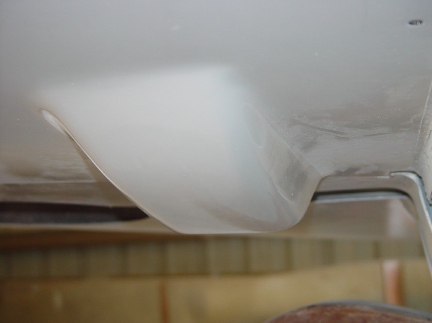
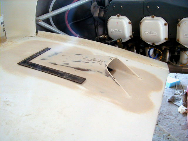
| Oil cooler cavity in wing root with hole cut into wing for inlet. | Starting to shape the inlet scoop. | Oil cooler inlet, bottom view. | Oil cooler inlet, inboard side view. Note angled inlet to provide the maximal opening when increasing angle of attack as when climbing. A similar cant is built into the induction air scoop as described in the captions to follow. |
|
|
|
|
|
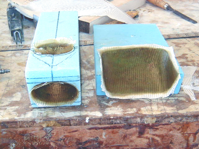
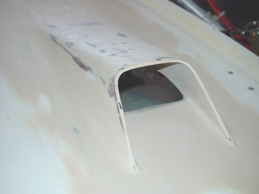
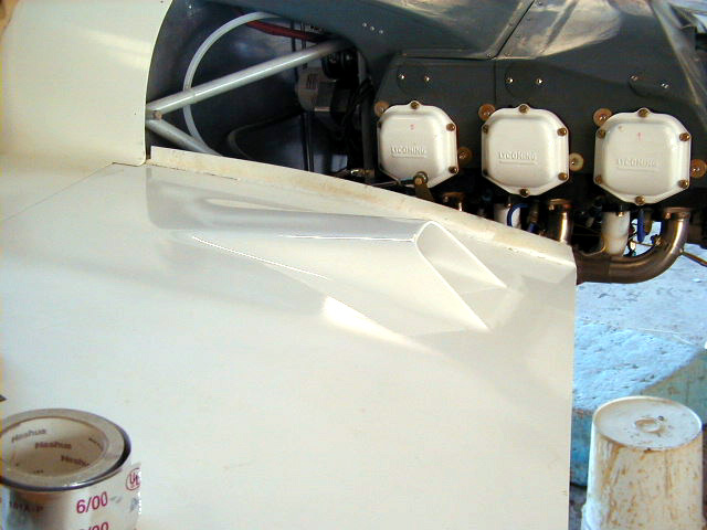
| Induction Air scoop, inboard side. | Induction Air scoop, view from outboard side. Note shaped form of the scoop between the inlet and the wing which raises the opening off the surface of the wing to put the intake outside of the boundary layer. In theory, this should allow faster moving air to be pushed into the scoop. The "pillar" is set back from the opening and shaped in a taper to 1) decrease inhaling water that may be washing back under the strakes and 2) allow the boundary layer to split around the base of the scoop, hopefully decreasing the amount of disruption in flow and therefore drag. The opening is canted to provide the maximal opening when climbing, as is the oil cooling inlet also seen on this page. | Throats of scoops glassed with layer of BID. | Throat of inducation air scoop. |
|
|
|
|
|
| View of inboard side of induction scoop. | View of inboad side of oil cooler inlet. | ||
|
|
|
|
|
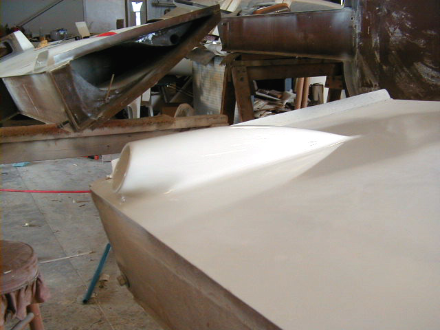
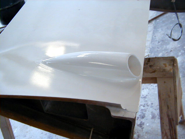
| Inducation air inlet now with primer. | Oil cooler inlet now with primer. | Finished induction air inlet. | |
|
|
|
|
|
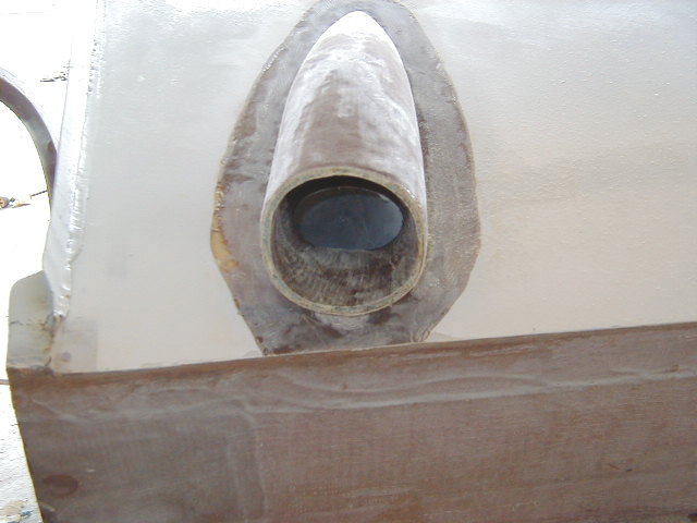
| Another view of the air inlet showing its nice contours. | Finished oil cooler inlet. | Another view of finished oil cooler inlet. | Hole upper wing surface to vent air passing through the oil cooler. |
|
|
|
|
|
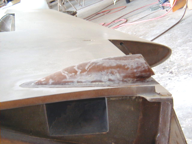
| Oil cooler outlet formed from foam. Area of wing to which it will be attached is sanded. | Shaped foam core of oil cooler outlet in position, ready for glassing over. | Oil cooler outlet glassed. | Side view of oil cooler outlet glassed. |
|
|
|
|
|
| Air induction inlet in primer looking from the front. | Air induction inlet in primer looking from the rear. | Oil cooler inlet in white primer looking from the front. | Oil cooler inlet in white primer looking from the rear. |
|
|
|
|
|
| Oil cooler outlet on top of wing being prepped for final primer. | Oil cooler outlet. | Oil cooler oulet in final primer. |
 Comments, questions, and suggestions are welcome! email: rich@rguerra.com
This page visited times.