

This section continues the modifications to and installation of the engine cooling system. Given how my engine was installed (placed such that the prop is centered in the rear hole of the cowling) the top part of the plenum interferes with the upper cowling. This requires the plenum to be "lowered" by removing a piece and reclosing it. A bit of a hassle, but this leads to not having to modify the lower cowling to fashion bumps to clear the alternator and fuel elbow on the bottom of the fuel servo, and allows the prop to sit a little high in the cowling. Better to modify the plenum right off, to avoid the necessity of further modifications to the cowling.
Step by step, the process of installing the NACA scoop slip joints, the modified cooling ducts and plenum and plenum baffles is illustrated. Note the modifications of the ductwork to improve air flow over the foremost cylinders.
Click on thumbnails to view larger versions of the pics!
2015 cheap best swiss rolex,panerai,iwc,hublot,tag heuer,breitling,patek philippe,omega Constellation watches,omega DeVille watches,omega Seamaster replica,top quality bvlgari,cartier,chopard,corum,franck muller,longines,tissot,u-boat,ulysse nardin,versace,glashutte,graham jaeger lecoutre.we also keep these watches entire brands:audemars piguet,breguet.
|
|
|
|
|
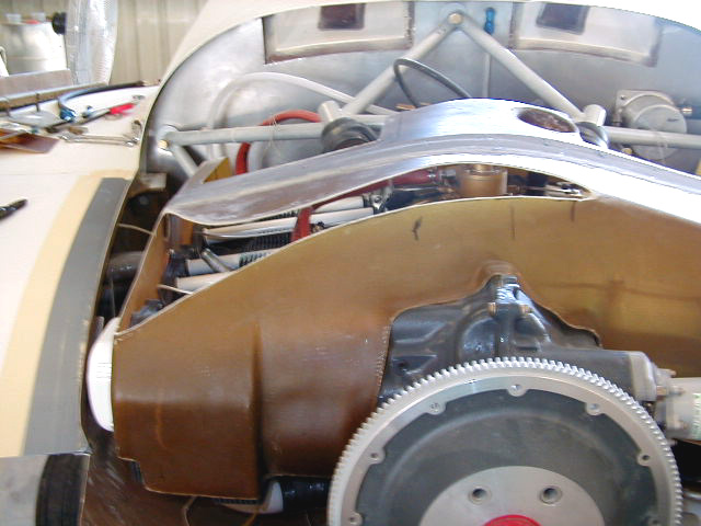
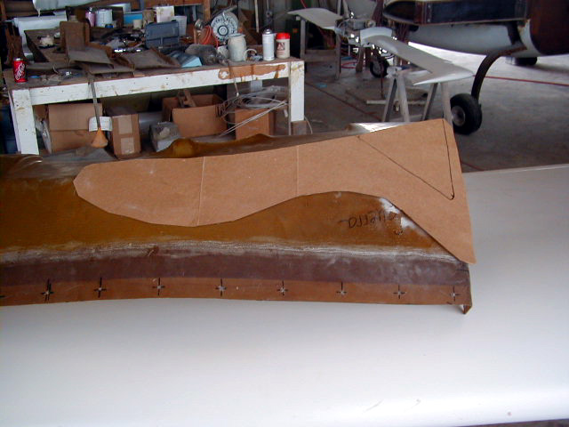
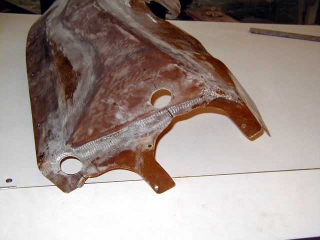
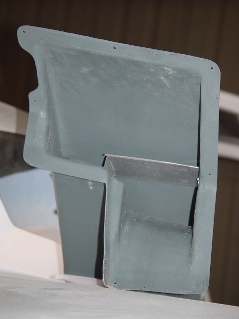
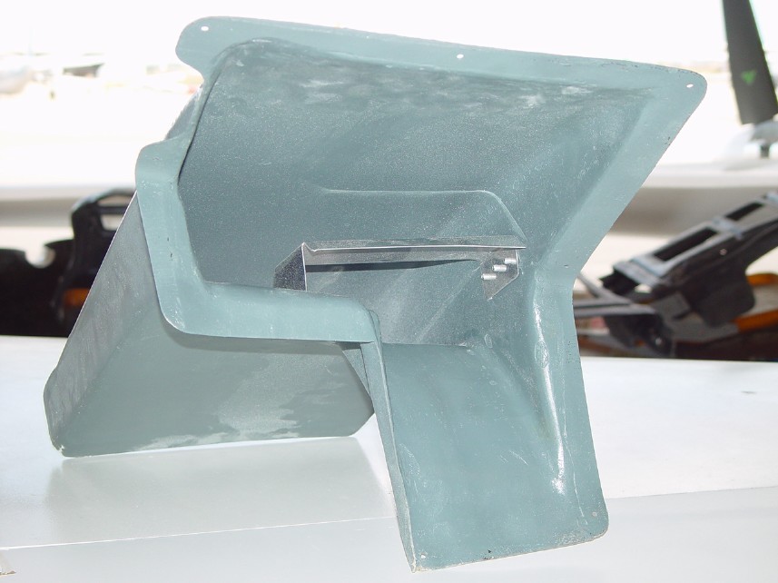
| Plenum cut at areas contacting the upper cowling. This area is removed and the plenum patched over to allow proper fit within cowling. This prevents having to modify the cowling to fit engine in place with its cooling system. | Another view of modifying the plenum to fit into the cowling. | Cardboard is shaped to fill in the hole. | ... covered with duct tape in anticipation of glassing over to reform the plenum. |
|
|
|
|
|
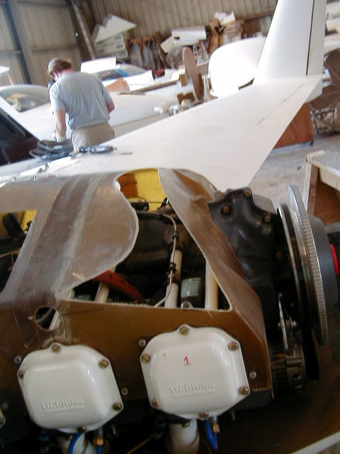
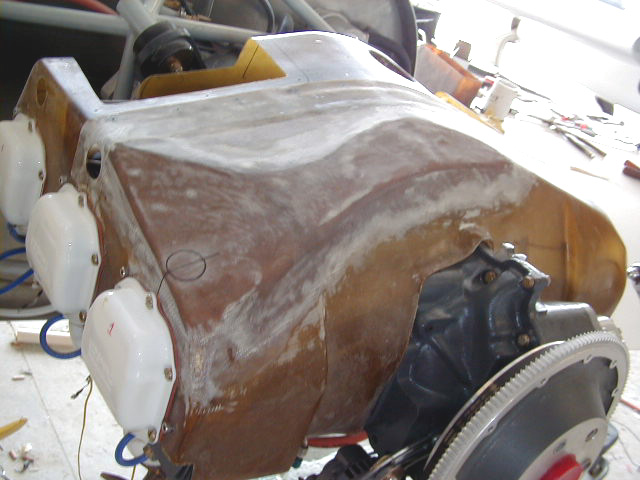
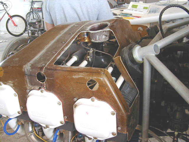
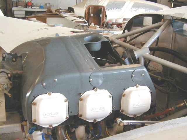
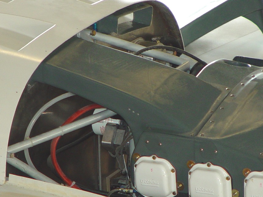
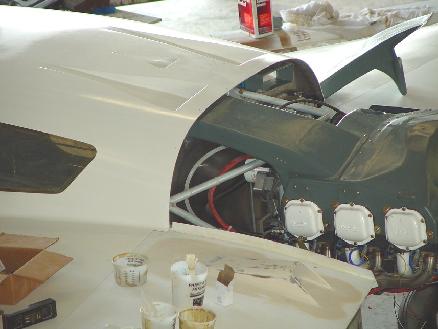
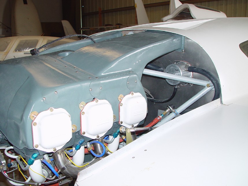
| Plenum seen after patching over the hole made to allow proper fit inside cowling. | Last spark plug access port added in modified portion of plenum. | Plenum refitted onto engine, ready for installation of ducting. | Plenum ready for installation of ducts to direct air from the NACA scoops into the plenum and over the cylinders. |
|
|
|
|
|
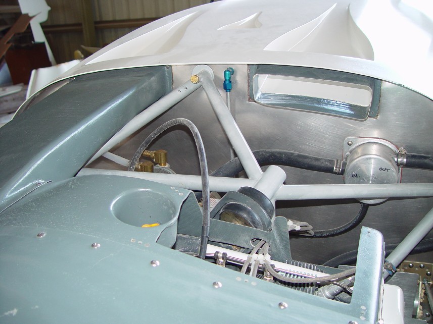
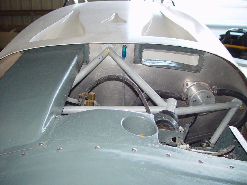
| NACA scoop slip joints, ready for installation of ductwork. | Slip joint for NACA scoop seen. Pilot side cooling duct in place. | Hangar 18 molded NACA duct. Note the diverting baffle right center. This diverts a portion of air over the first cylinders which are the hardest to cool. This explains the modification such that the opening of the front half of the plenum is so large. This allows air to flow downwards with minimum change of angle. | Another view inside cooling duct with metal baffle. |
|
|
|
|
|
| Various views of cooling duct system before final duct in place. | |||
|
|
|
|
|
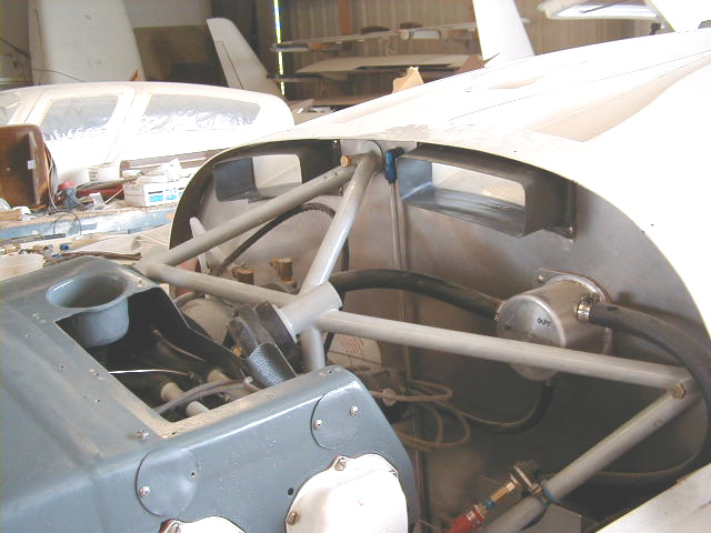
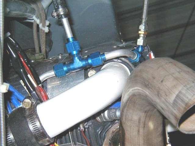
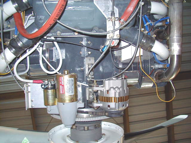
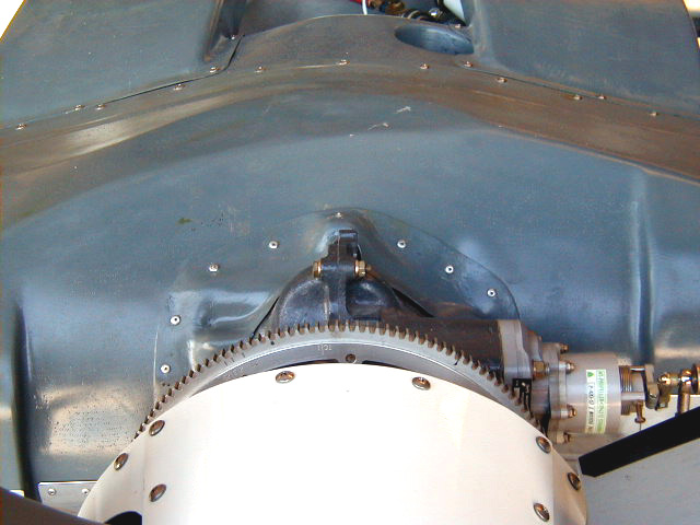
| Cooling system completed! | Forward plenum baffling around seen left center of photo with safety wire extending back. NACA scoop duct seen top center. Firewall located forward from top of photo. | View from below engine. Prop to bottom of photo. Alternator and start bottom center, Reiff HotStrip heater seen at top center. Aft plenum baffling seen wrapped around aftmost cylinders, safety wired into position. | Aft end of the cooling plenum leaked air and potentially decreases amount of cooling possible by the air flow from NACA scoops on roof. A small fiberglass part is fashioned and riveted in place to seal off this space. |
 Comments, questions, and suggestions are welcome! email: rich@rguerra.com
This page visited times.