

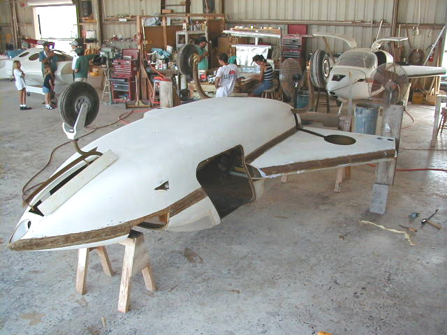


The photos below are arranged chronologically and illustrate the process of constructing the remaining major structural elelments. The difficult layups inside the rear of the strakes is of importance. This bonds the top of the strake to the center spar and "closes the box" defined by all the top, leading edge and bottom of the strake and center spar. This forms the enormously strong torsion box to which the wings are connected.
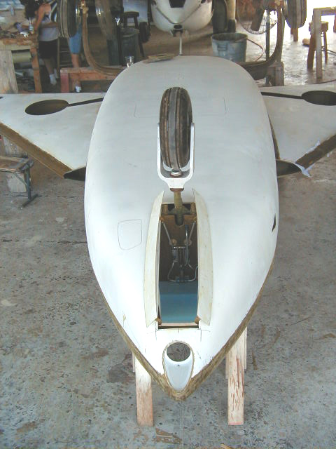
The installation of the nose landing light and front cabin air inlet is also illustrated.
Click on thumbnails to view larger versions of the pics!
2015 cheap best swiss rolex,panerai,iwc,hublot,tag heuer,breitling,patek philippe,cheap omega replica,omega Constellation watches,omega DeVille watches,omega Seamaster replica,omega replica for sale,top quality bvlgari,cartier,chopard,corum,franck muller,longines,buy omega replicatissot,u-boat,ulysse nardin,versace,glashutte,graham jaeger lecoutre hublot big bang replica.we also keep these watches entire brands:audemars piguet,breguet,hublot replica
|
|
|
|
|
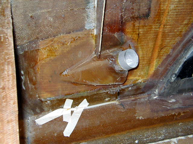
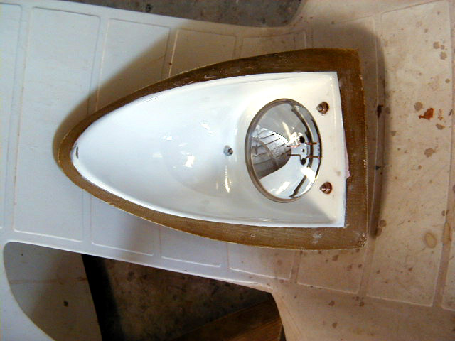
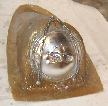
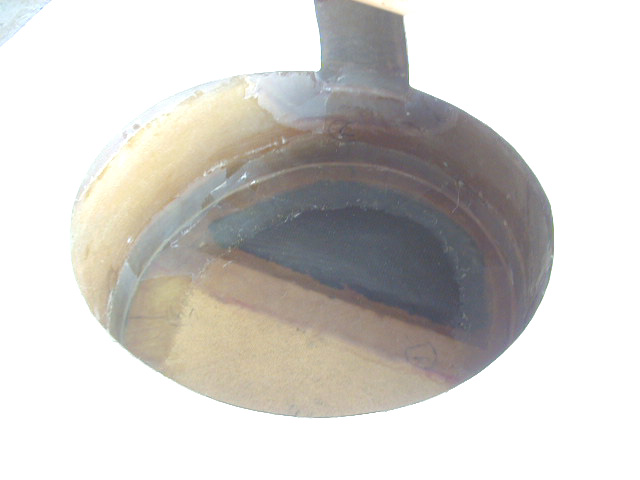
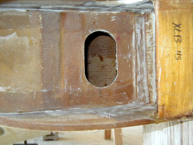
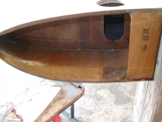
| Front cabin air inlet scoop. | Inside view of front cabin air inlet. | Landing light assembly. | |
|
|
|
|
|
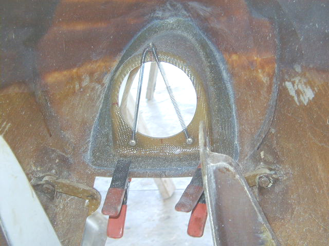
| Landing light housing installed. | Landing light assembly installed. | N724X upside down to facilitate finishing the roof and inside strakes. | |
|
|
|
|
|
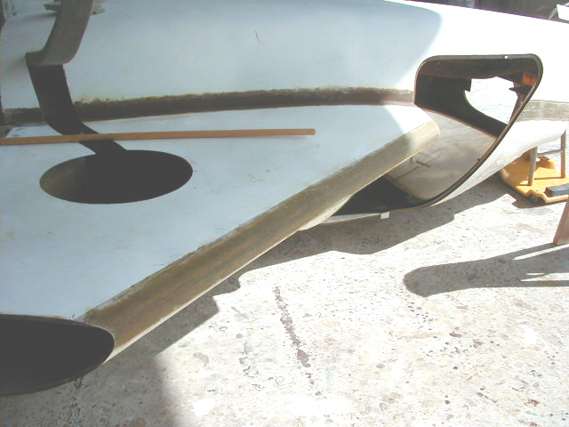
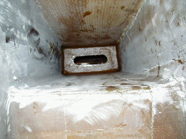
| Layers of BID across the leading edge of the strake to strengthen the bond between the top and bottom halves and further seal the fuel tanks. Peel ply seen in place. | Strake leading edge layup seen after removal of peel ply. | Layups of BID around edges of wheel well to strak top contact point. This further bonds the strake halves together and also helps insure fuel tank sealing. | |
|
|
|
|
|
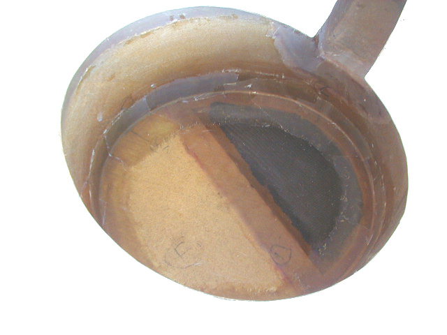
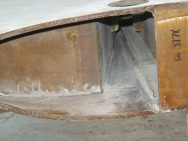
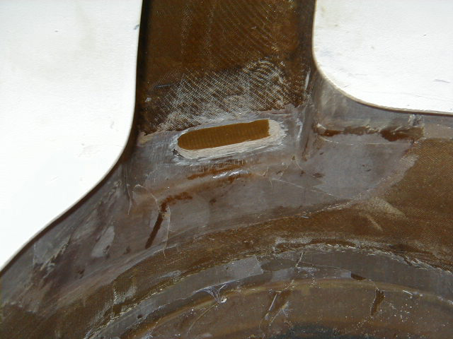
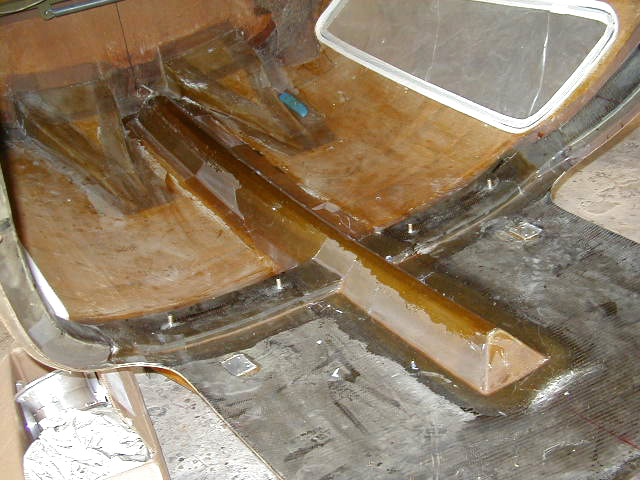
| Another view of wheel well layup. | The hardest layup in the project! This is the section of the strake BEHIND the fuel tank. The plane is inverted so the top half of the strake is seen at the bottom of the picture. The outboard bulkhead of the fuel tank is seen at the left and the center spar is seen on the right. This area must first be sanded to rough up the surface to insure good bonding of further layup. The groove seen must be then filled in with epoxy/milled fiber/cabosil and a radius formed at the edge of the rear fuel tank bulkhead to allow for layups. | Hanger 18 special tooling!! A little snading block on a stick and a squeegee attached to end of a PVC pipe allows aforementioned preparations to be performed. | Another view of the daunting task. The little flange for the inboard bulkhead seen. This is there since we won't be able to reach behind it to do layup on back side of bulkhead. Instead, the back of the bulkhead is coated with structural adhesive and layuups are placed on the font side after pressing the bulkhead against the flange. |
|
|
|
|
|
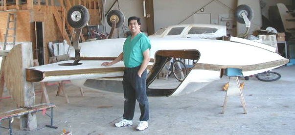
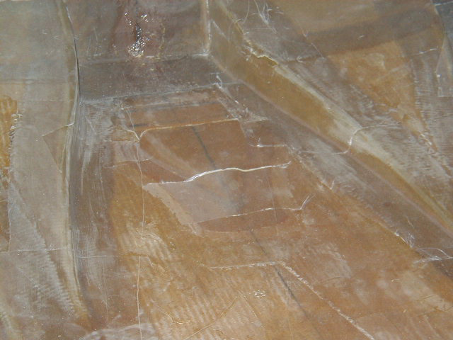
| Layups peel plyed after being set into position. Layers of BID are wetted out on plastic. The outermost end is placed into postion and the remainder is worked inch by inch into postion. A very long straightedge is used to push the fiberglass into position inch at a time! It helps to find someone with long, skinny arms to do this! | Layers of BID also applied to outboard fuel bulhead edge. | The Plane & I. | Inboard bulkhead bonded into place as discussed above. |
|
|
|
|
|
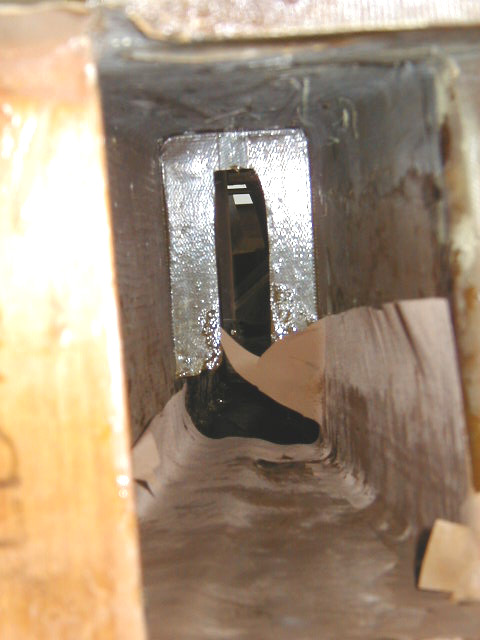
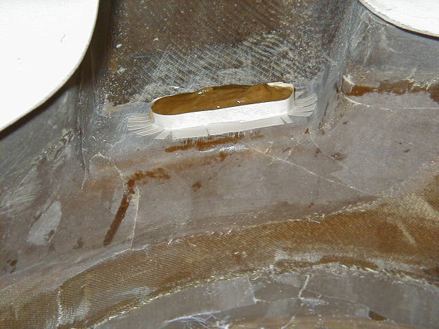
| Outboard small bulkhead cobo'ed into place | ... and then glassed in. You can reach around through the hole to lay in the fiberglass binding the backside to the strake bulkheads. | The final step: Layers of triax to stengthen the outboard edge of strakes. | Forming the up stop point for the main gear. |
|
|
|
|
|
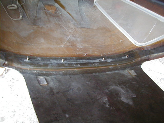
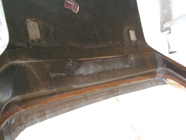
| Main gear stop cured up. | April 24, 2001 - Aft overhead carbon beam installed. | A Hangar 18 enhancement: Carbon fiber reinforced switch panel installed bridging across the two forward carbon beams. This forms a full arch and the forward support for the enhanced "roll cage" for the cabin. | Overhead air intake inlet seen in between two large engine air intake NACA scoops in cabin roof. |
|
|
|||
| Overhead cabin fresh air plenum. |
 Comments, questions, and suggestions are welcome! email: rich@rguerra.com
This page visited times.