


October - November 2001 - On the Home Stretch!! Below are lots of final details and finish work as the plane takes shape. Taxi testing and FAA inspection not far now!
Photos of wiring as it progresses, pitot-static system added 11/30/01.
Click on thumbnails to view larger versions of the pics!
2015 cheap best swiss rolex,panerai,iwc,hublot,tag heuer,breitling,patek philippe,omega Constellation watches,omega DeVille watches,omega Seamaster replica,top quality bvlgari,cartier,chopard,corum,franck muller,longines,tissot,u-boat,ulysse nardin,versace,glashutte,graham jaeger lecoutre.we also keep these watches entire brands:audemars piguet,breguet.
|
|
|
|
|
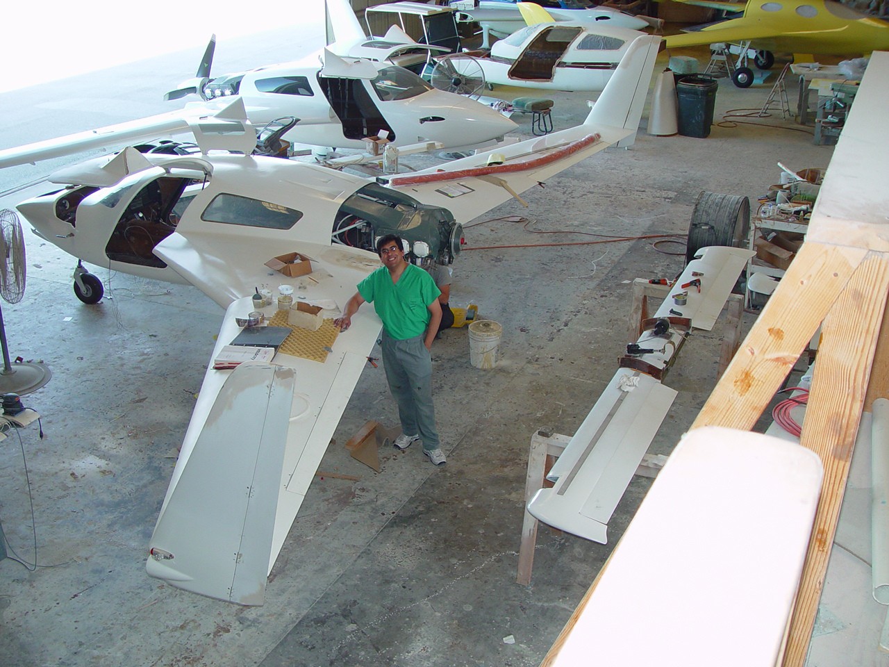
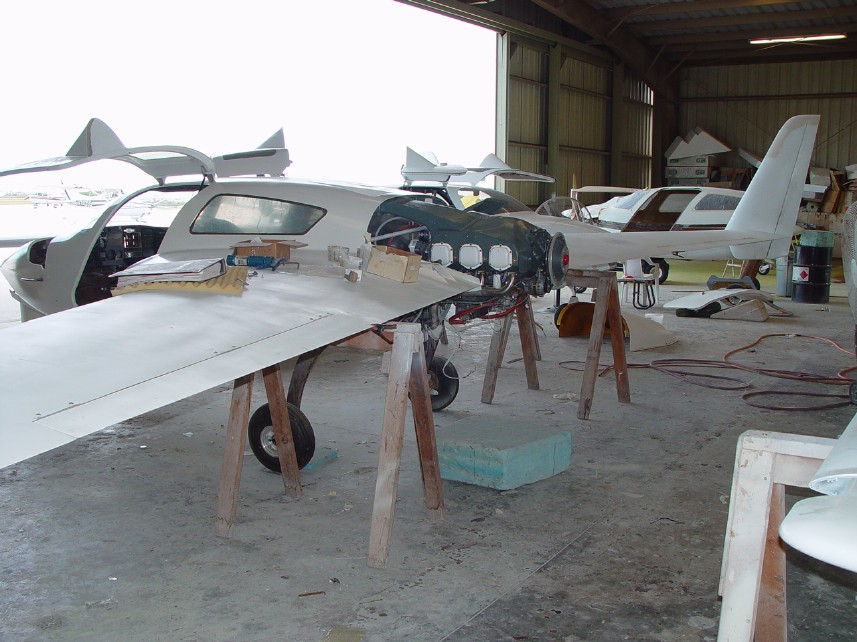
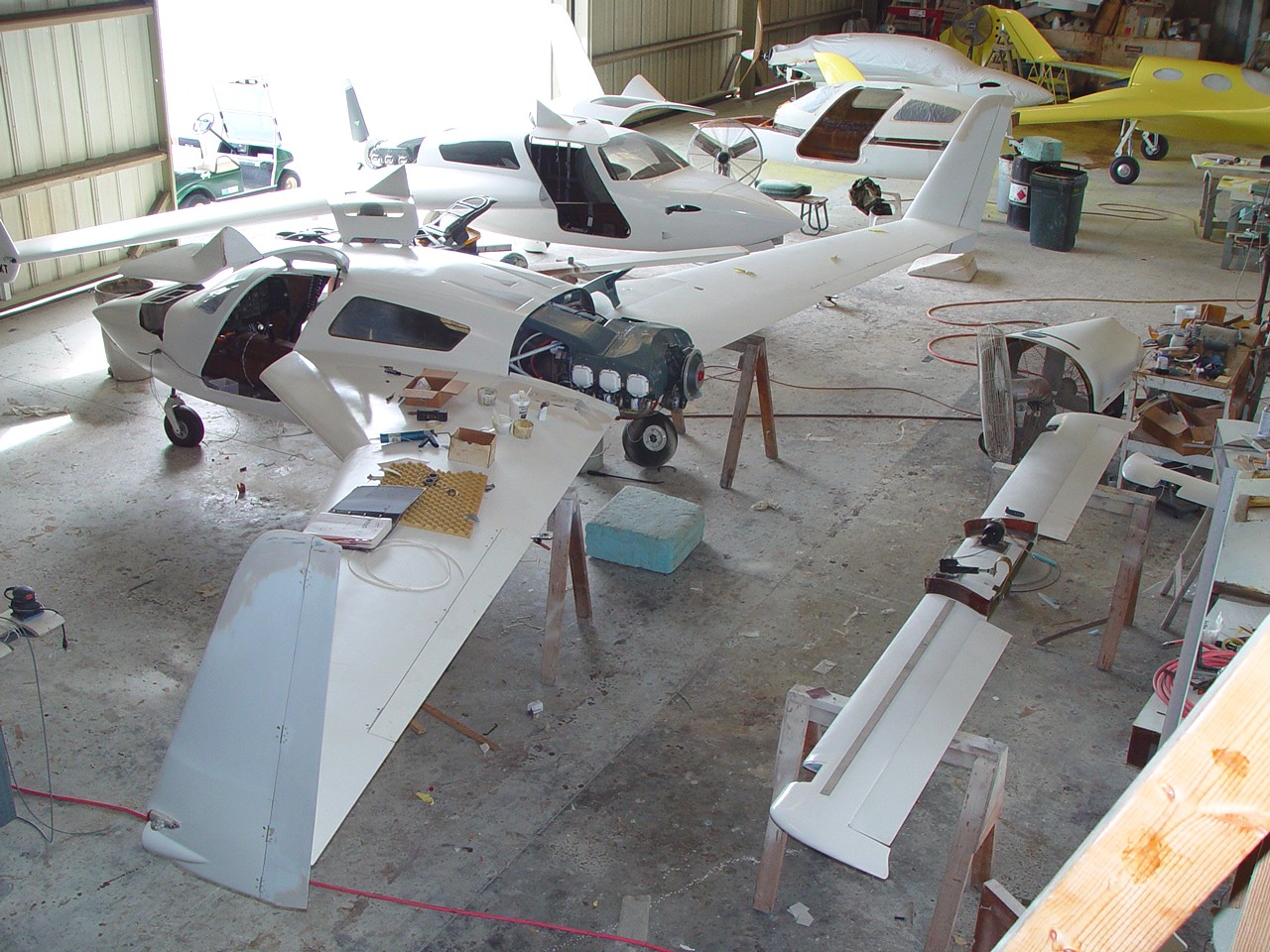
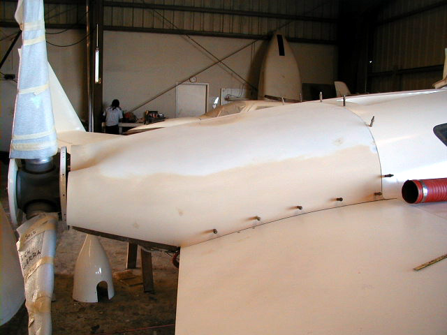
| 10/31/01 - Some shots of the plane. Getting closer to FAA inspection! | Overview of the shop. Ken Tonyman's beautiful XL seen next to N724X. The yellow plane in the background is Alan Shaw's Atlantica. | ||
|
|
|
|
|
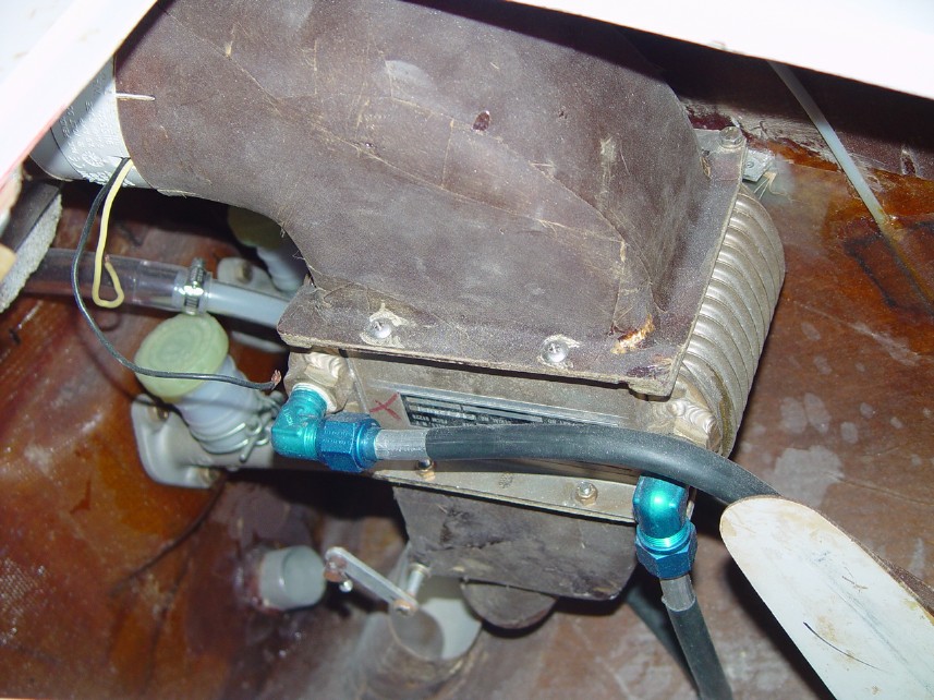
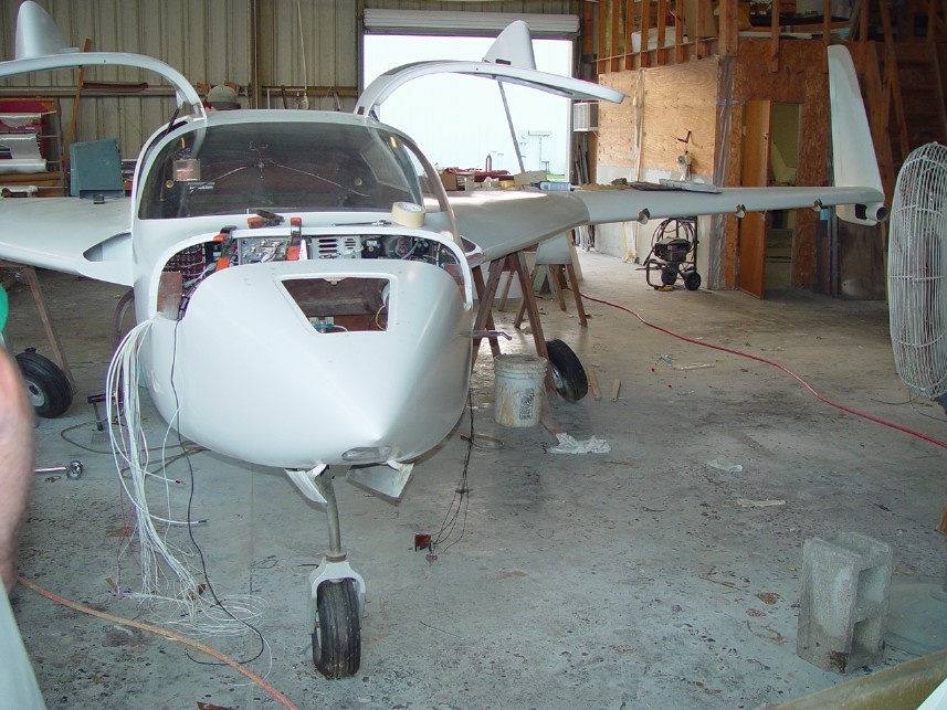
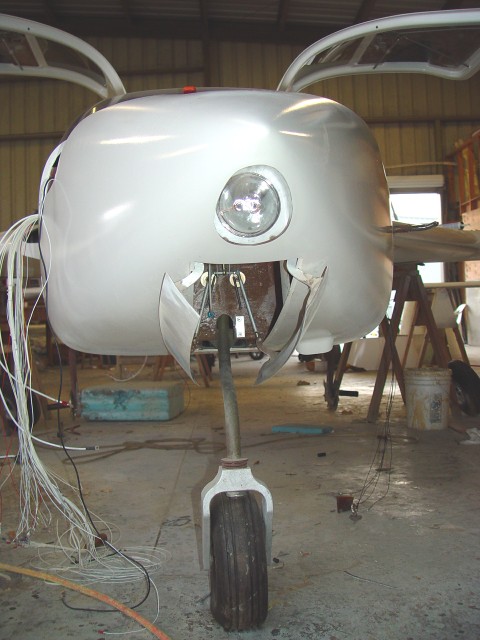
| Side view - lower winglet copilot side still needs modification. | Cabin heater assembly with bilge fan as detailed in previous sections. | N724X from the front. Lots of wiring to be done!! | View of the rear of the cabin and forward aspect of the firewall. Details of the fuel tank vent system (top center, 'cross-shaped' fitting), landing gear, fuel lines (seen mid center each side entering sump tank), sump tank (lower center), etc. seen. |
|
|
|
|
|
| Glideslope antenna on floor under pilot's seat. Marker beacon antenna seen at top along keel. | Overhad fresh air plenum with RVR 300a map light, air vent and Perko light seen. | ||
|
|
|
|
|
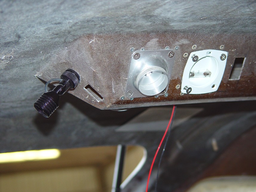
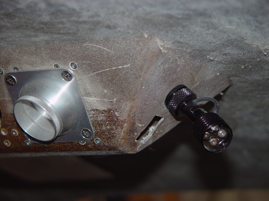
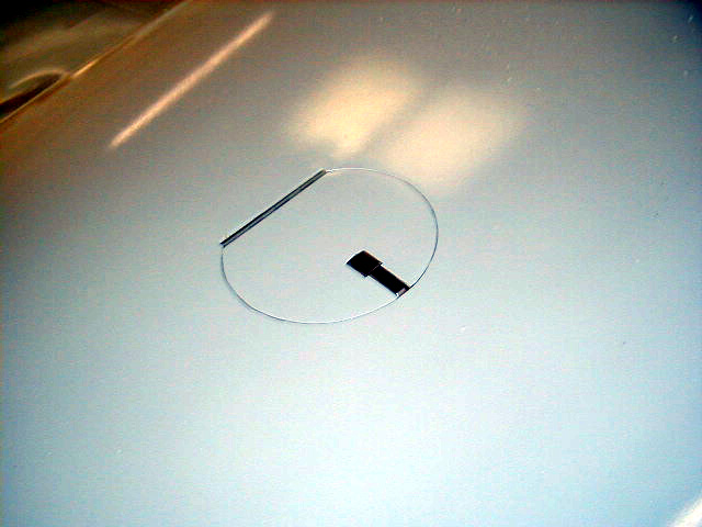
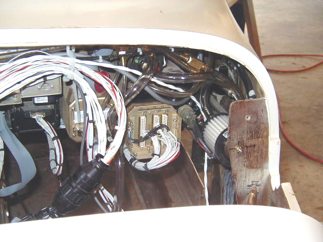
| Pitot tube and static port. | Antenna leads seen. | Wiring slowly proceeding! | Headset jacks mounted in keel on wither side. The mounts are premolded Hangar 18 parts as commercially available versions didn't seem to do the job. These allow jacks to lie nearly flush against the keel, out of the way. The forward seat jacks for pilot and copilot are located just behind the front seats. |
|
|
|
|
|
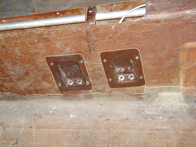
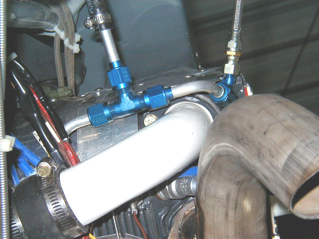
| Left wingroot with steel baffles in place enclosing the wingroot oil cooler. The firewall material protects the wingroot as this portion of the wings is within the engine compartment. | Copilot side wing root seen with protective lining. Air induction scoop entry point seen. | Oil door closed and in finish primer. | Oil door seen with cowling in place. You can see the plug for the Reiff engine heater also. |
|
|
|
|
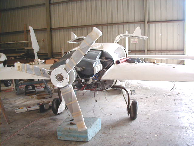
|
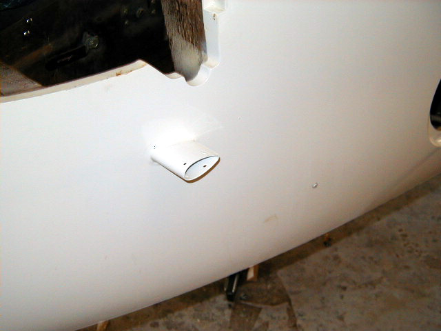
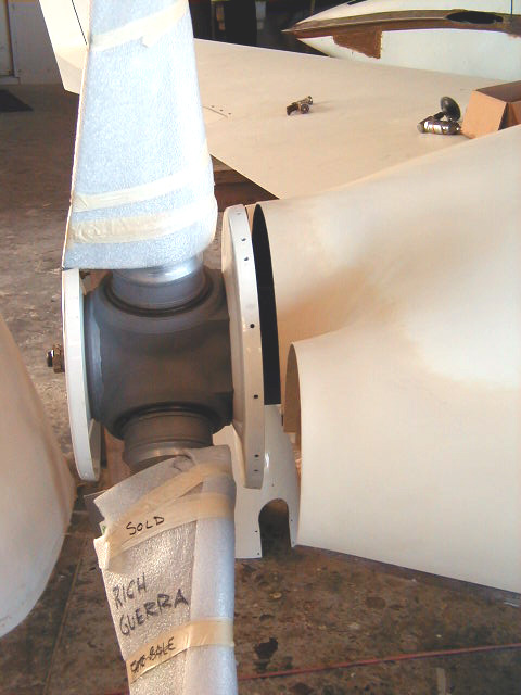
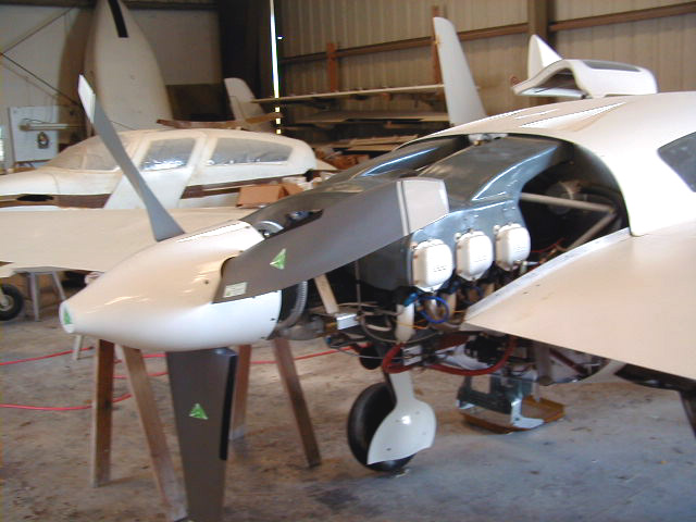
| Pitot tube mount primed and finished. | The 3 blade MT Hydraulic propeller is mounted!!!! | Lower cowl in finished primer. | Cowlings cleaned up and primed. |
|
|
|
|
|
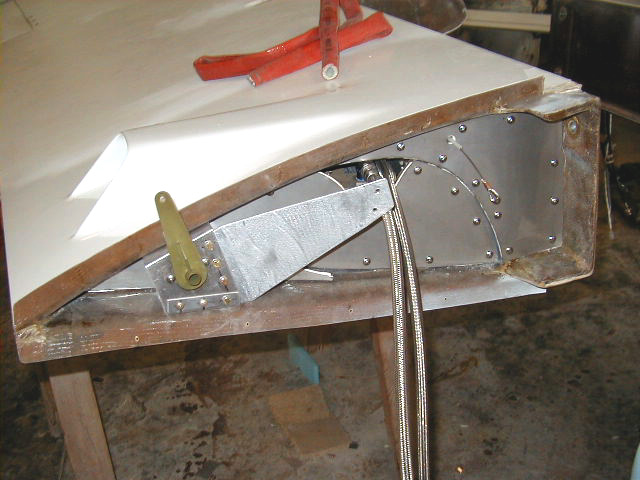
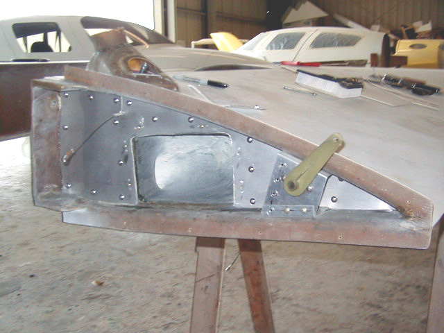
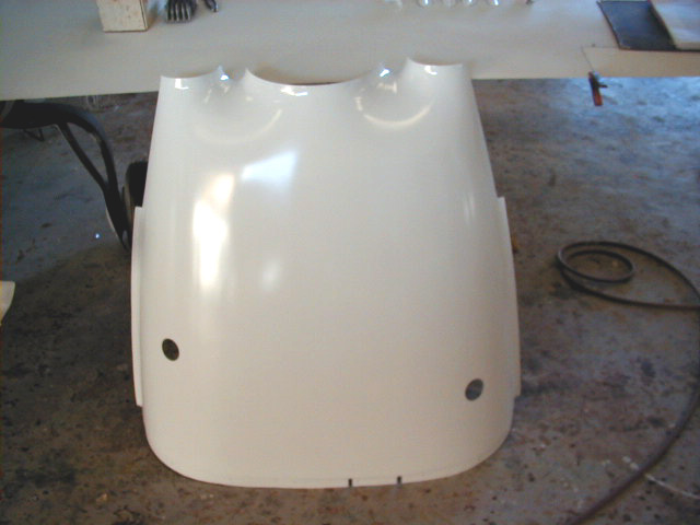
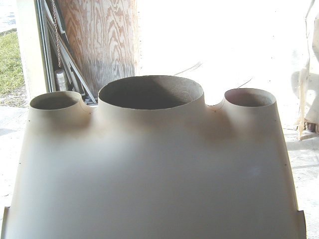
| Cowlings fit onto plane and final adjustments made. | Note clearance from prop. | Forward plenum baffling around seen left center of photo with safety wire extending back. NACA scoop duct seen top center. Firewall located forward from top of photo. | |
|
|
|
|
|
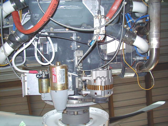
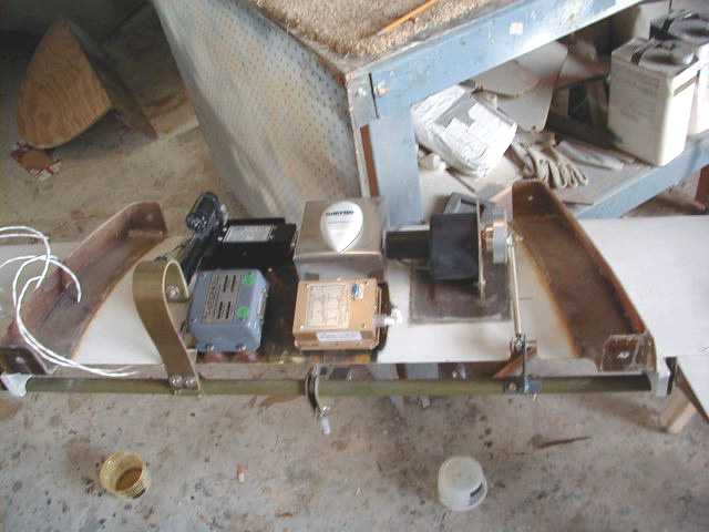
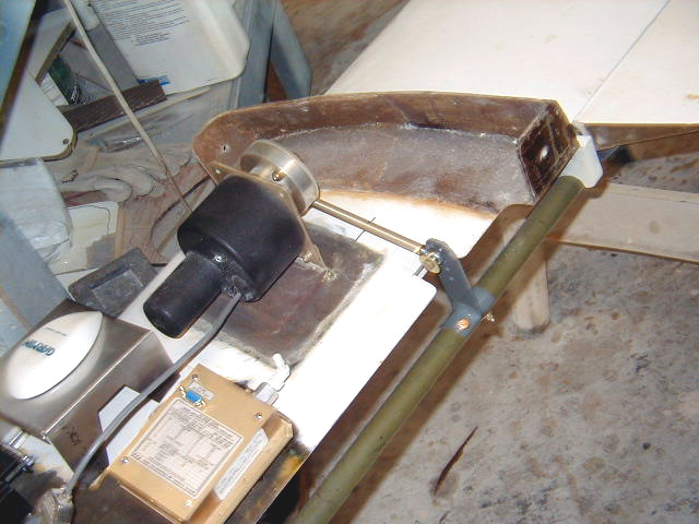
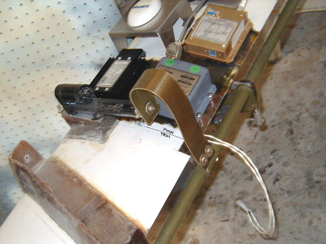
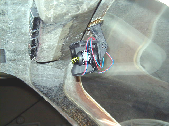
| View from below engine. Prop to bottom of photo. Alternator and start bottom center, Reiff HotStrip heater seen at top center. Aft plenum baffling seen wrapped around aftmost cylinders, safety wired into position. | The top of the canard is a busy place! Here is a convenient place to mount a number of key components. On the left is the pitch trim system and Aerotronics annunciator module, in the center, the Garmin GNS530 antenna and the Trans-Cal altitude encoder to feed info to the MX20 for use in the terrain clearance feature and on the right, the S-Tec autopilot pitch servo. The second encoder was unfortunately necessitated due to difficulty making all vendors' equipment talk to one another. The MicroEncoder is capable of sending data out at EITHER 1200 baud OR 9600 which makes it easy to interface with just about anything. It drives the Garmin transponder and GNS530. Unfortunately, the MX20 REQUIRES altitude input at 1200 baud even though any of its ports can be set to operate at 9600 for other purposes. Once a port is designated to be altitude input, it is hard-coded to run at 1200 and there isn't any way to change it. To change this "feature" would require a tweak in its software which I can't access. Without the encoder input, NO Terrain feature on MX20 which was one of the main reasons for its installation. Given the information beyond simple altitude generated by the MicroEncoder, it made more sense to connect to GPS and transponder and provide separate source of data to the MX20. | Closer view of S-Tec pitch servo. Note fitting on elevator torque tube made with multiple holes to allow adjustment of the autopilot's lever arm if needed. | Closer view of pitch trim system. |
|
|
|
|
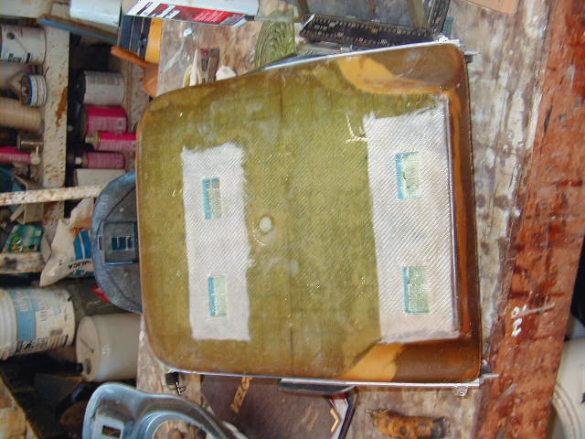
|
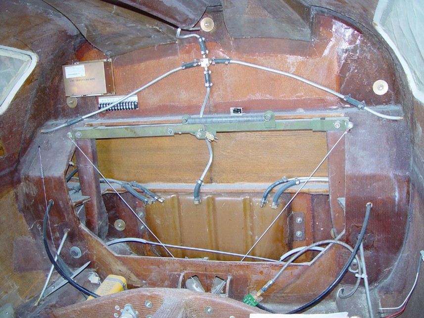
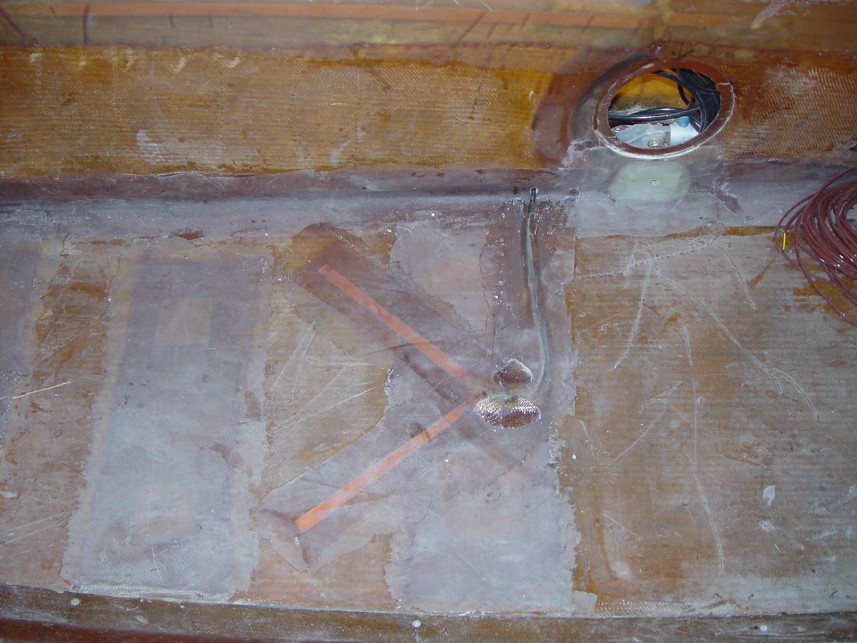
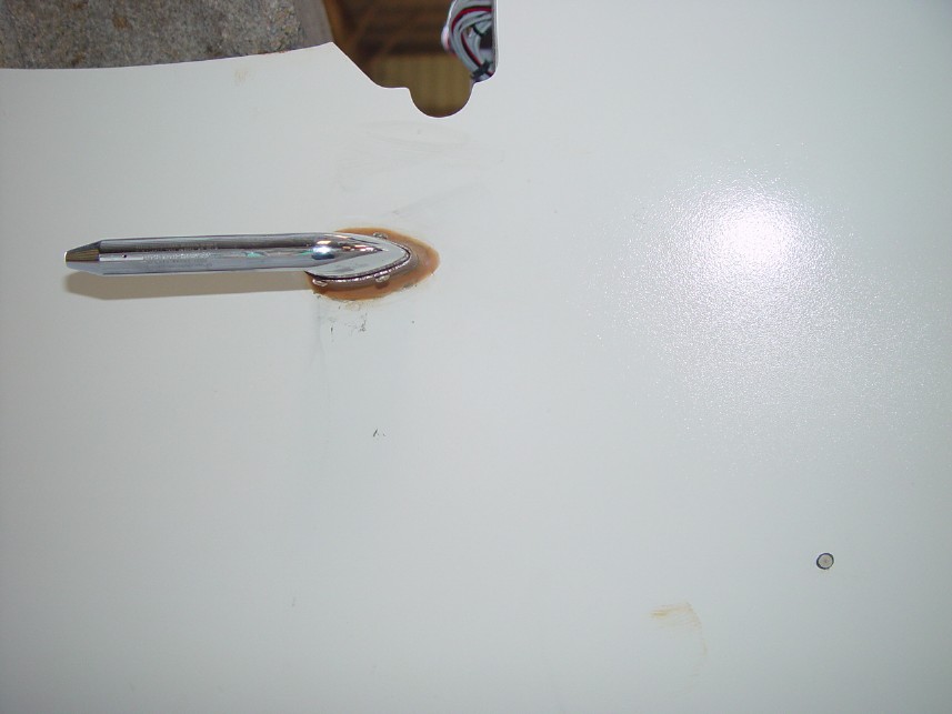
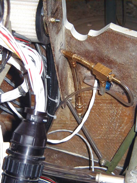
| SIRS compass mounted just aft of the overhead switch panel. It is forward enough to allow ease of viewing but not so much to obstruct the view out the windshield. | Front seat bottom hardpoints installation preparation. The hardpoints are imbedded into the seat rather than attached on the surface to avoid raising the seat higher. | Rear of panel viewed through canard cover. If you look closely, you can see plumbing for pitot, static and vacuum systems. | Moisture drain on static system line. |
|
|
|
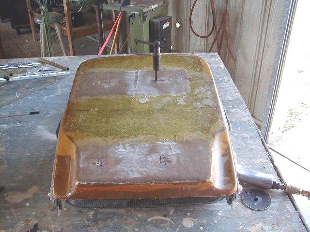
|
|
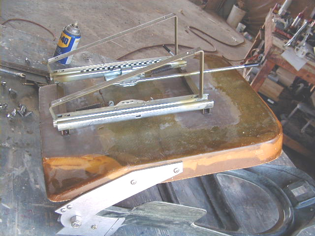
| Remote gyro for Sandel HSI placed just aft of the keel where it will be out of the way but still accessible for servicing. | 11/27 - The spinner is on!! Won't be long now!! | Tapping the hardpoints installed underside of front seat bottoms. | Installing the new seat slider. |
|
|
|
||
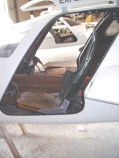
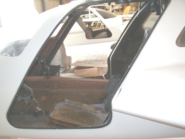
| Seat installed in place, shown as far forward as possible... | ... and as far aftward as possible. |
 Comments, questions, and suggestions are welcome! email: rich@rguerra.com
This page visited times.