
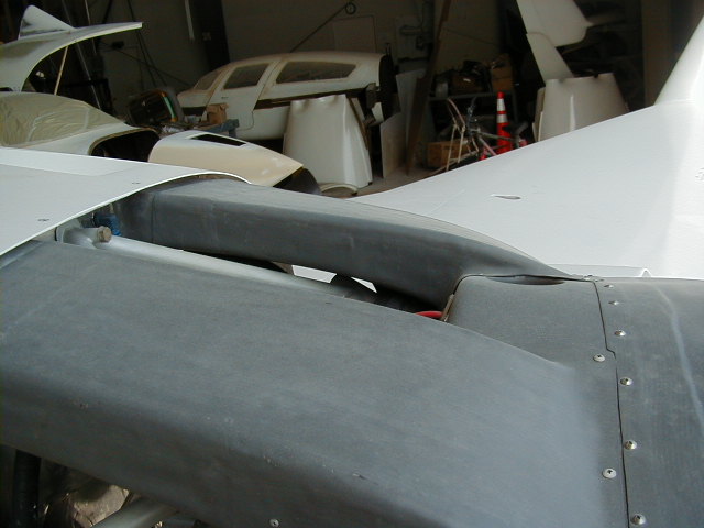
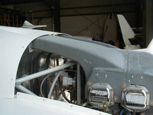
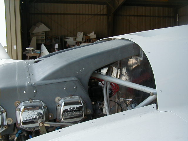

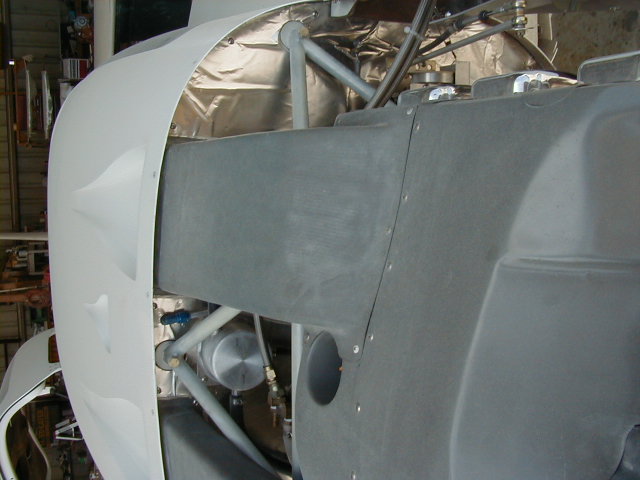
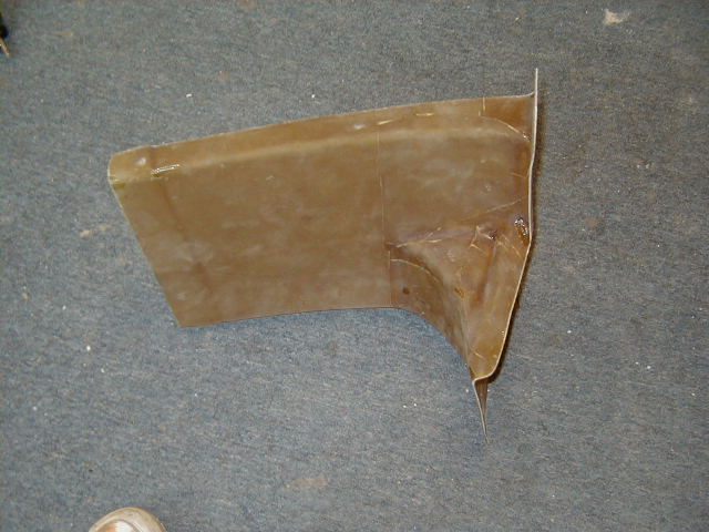


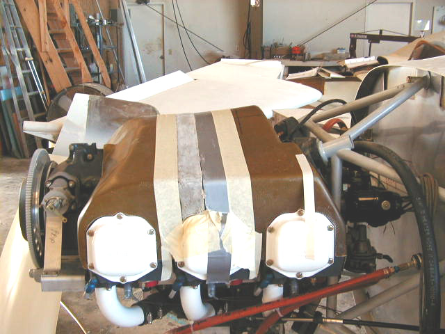

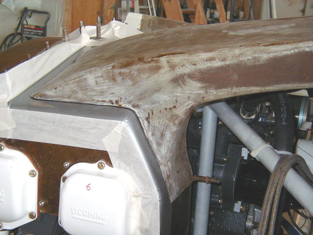
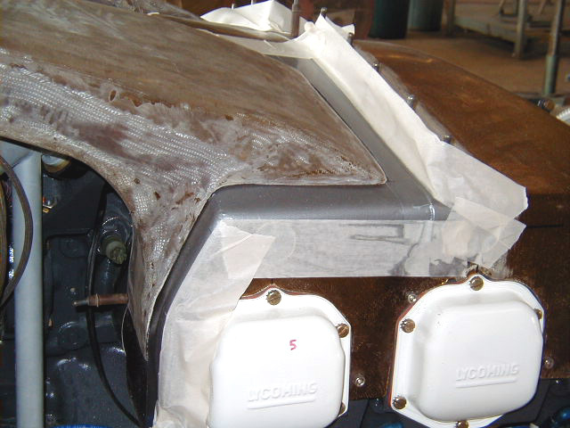
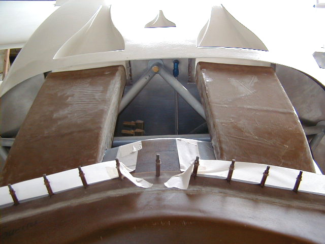
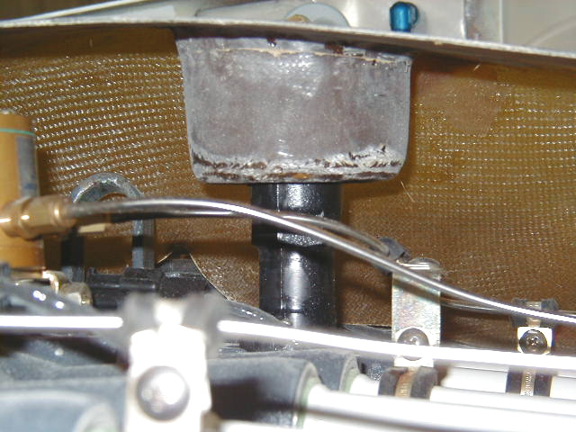


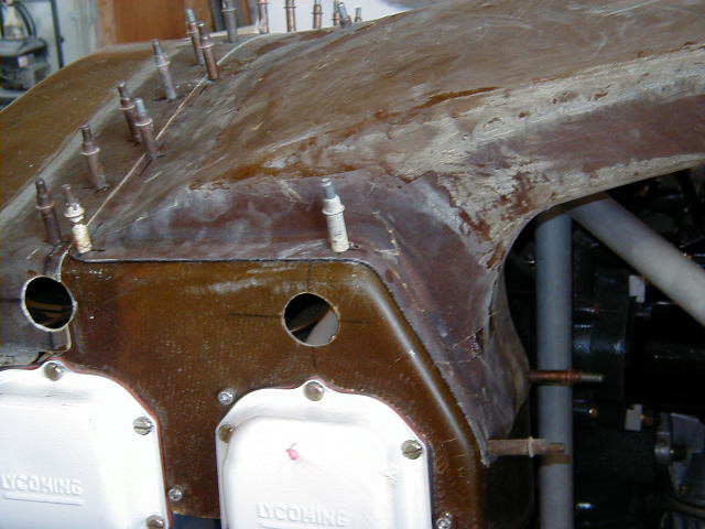


A Hangar 18 modification: the engine cooling system installed will leverage off the optimized NACA scoops in the upper fuselage. The first series of photos are of Ken Tonyman's spectacular XL, N99KT. The following pics detail the creation of the cooling duct parts and modification of the plenum to deliver efficient cooling air. This system has been used successfully on several Hangar 18 Velocity XLs. Some of the parts are molded from the hand shaped ductwork seen in N99KT below. Note that the ducts proceed from NACA inlet to plenum directly over the engine mount. This differs from the factory ducts which are shaped differently due to the use of larger scoops. Avoiding deviation from straight lines or constrictions in the ductwork as much as possible maximizes air flow and minimizes resistance.
Please see 'Engine Cooling System Part II' section for the completion of the installation of the engine cooling system and the modifications made to the factory setup.
Click on thumbnails to view larger versions of the pics!
|
|
|
|
|
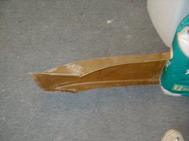
| N99KT - Inboard left duct. | N99KT - Inboard right duct. | N99KT - Outboard left duct. | N99KT - Outboard right duct. |
|
|
|
|
|
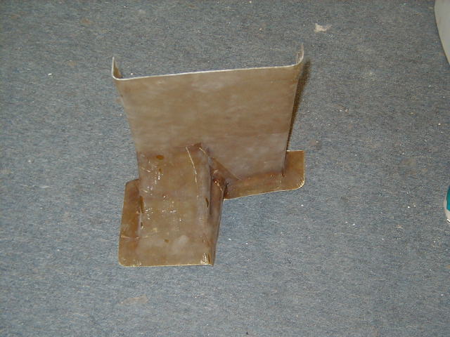
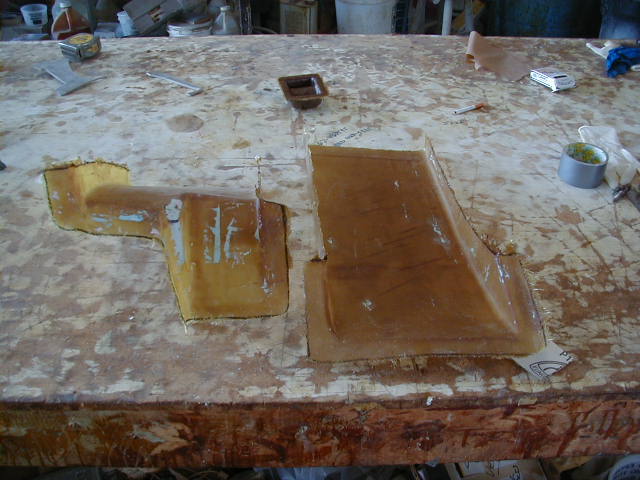
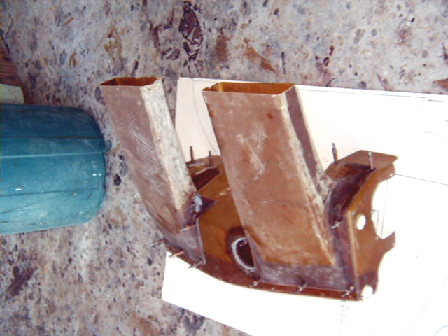
| N99KT - Top left duct. | N99KT - Top right duct. | Multiple views of the molded cooling ducts. These ducts are specially molded to mate with the Hangar 18 NACA scoops and modified factory plenum. | |
|
|
|
|
|
|
|
|
|
|
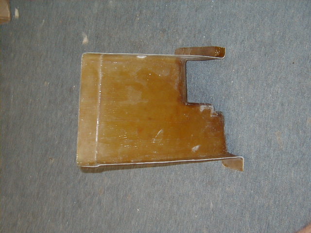
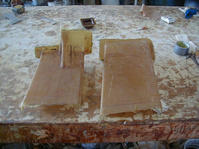
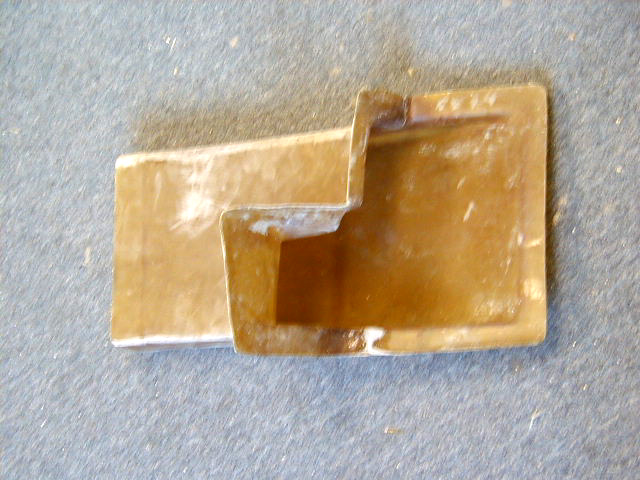
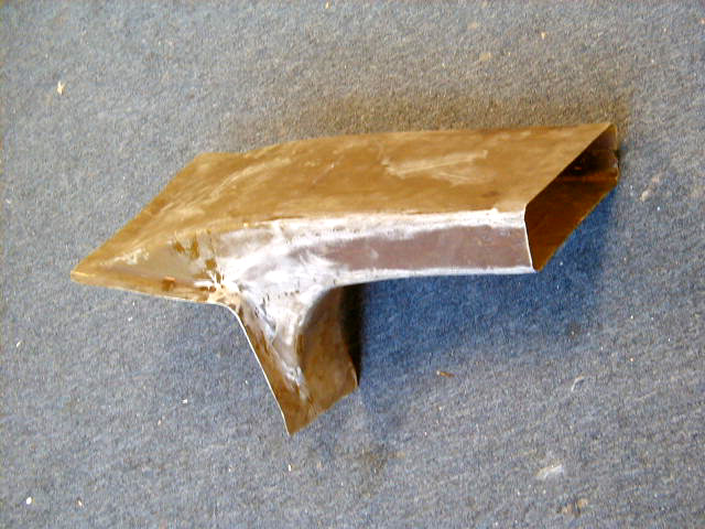
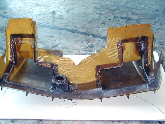
| inside of cooling ducts. | Outside of molded ducts. | ||
|
|
|
|
|
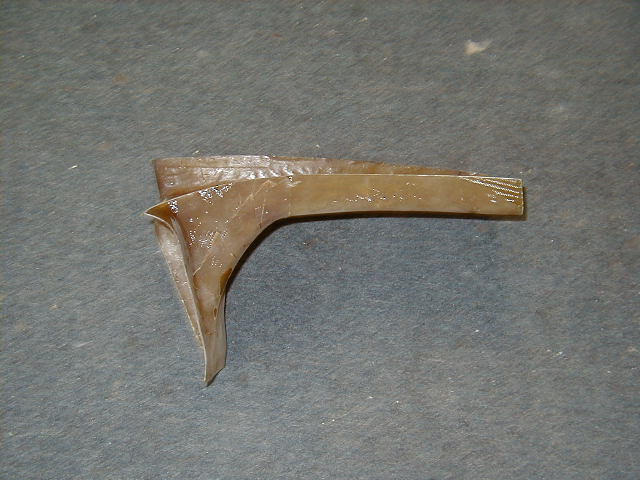
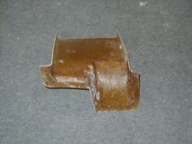
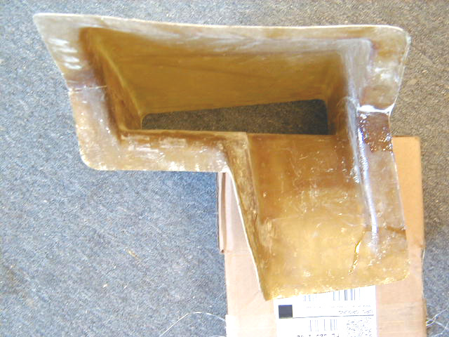
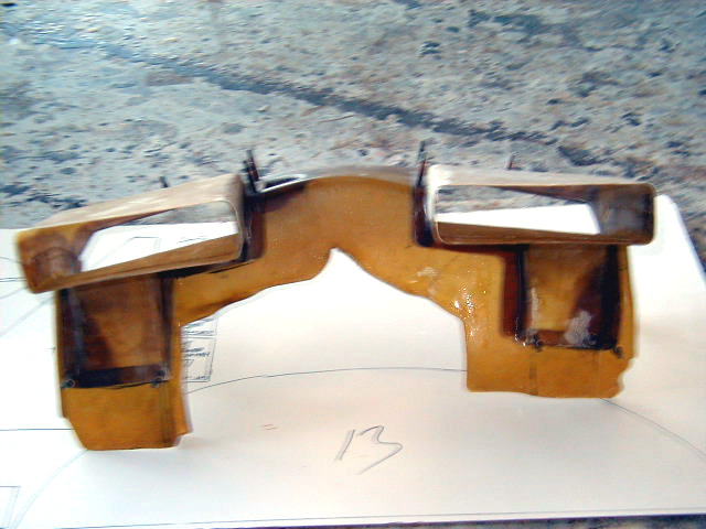
| Side view of molded ducts. | Cooling duct halves now joined. | Molded cooling duct viewed from plenum end. Although it isn't well seen here, the ducts are straight as possible with no constriction of the channel to maximize air flow passage. | |
|
|
|
|
|
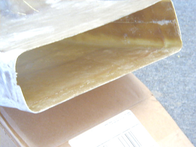
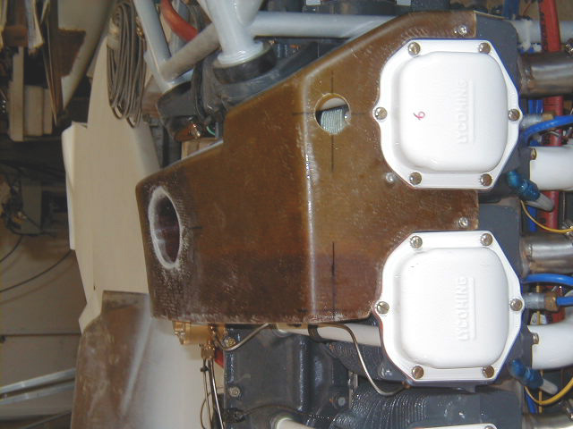
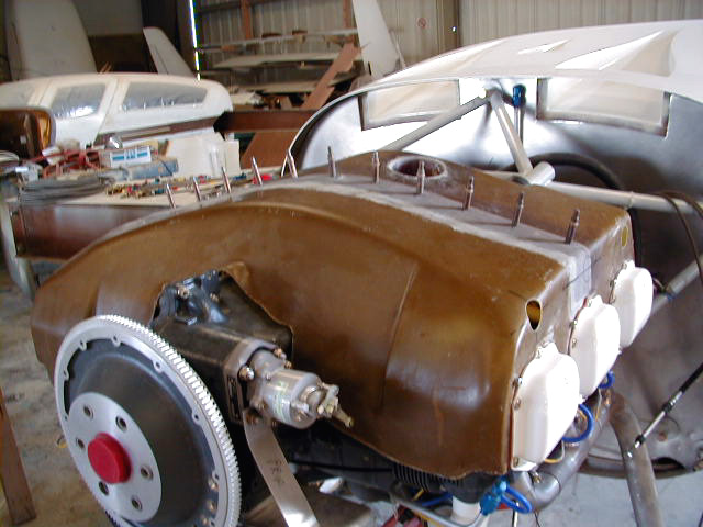
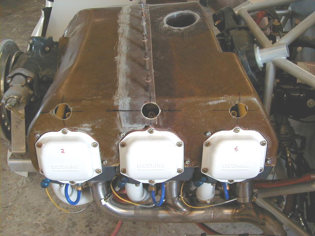
| Forward end of duct. Note here one can see the slightly widened mouth into which a slip joint connected to NACA inlet is inserted. This decreases vibration stresses on the ducts as they are not directly bound to the fuselage. | Cooling plenum fitted onto engine. | Front half plenum mounted. | Rear half plenum mounted. |
|
|
|
|
|
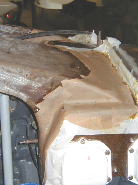
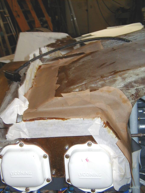
| Plenum mounted, side view. | Fitting of cooling ducts onto plenum. Modifications made to the front half seen below. Flanges for the molded ducts are fabricated in the next photos with layup made over the duct tape on the plenum. | Multiple views of fitting the ducts to plenum. | |
|
|
|
|
|
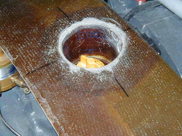
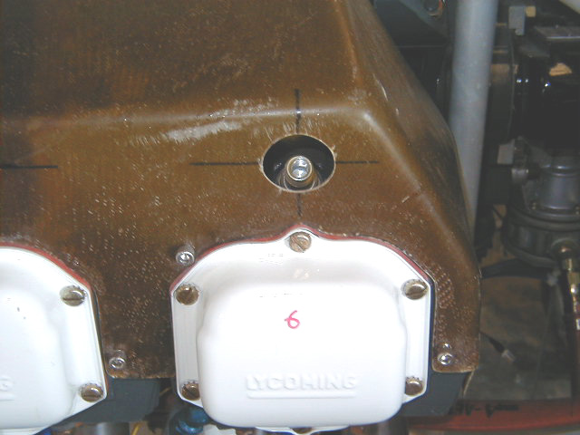
| Oil check access. | Oil check "cup", side view inside of plenum. | Spark plug access. | |
|
|
|
|
|
| Spark plug access plate in place. Will be secured with screws/nut plates. The holes are big enough to allow removal of spark plugs. | Ductwork flanges being laid up as noted above. | Final product - flanges seen that now perfectly mate to the front half of plenum. | |
|
|
|
|
|
| Duct now clecoed into position showing fit top plenum. Spark plug access ports also seen. | Front half of plenum. This graphically illustrates the size of the openings to the ducts connected to the NACA scoops. The intent is to minimize any impediment of flow from the scoops to the plenum. | inside view of front half of plenum, again illustrating the large size of the holes through which air entering from the upper fuselage NACA inlets passes. | Ducts clecoed into position to front half plenum, side view. |
|
|
|
|
|
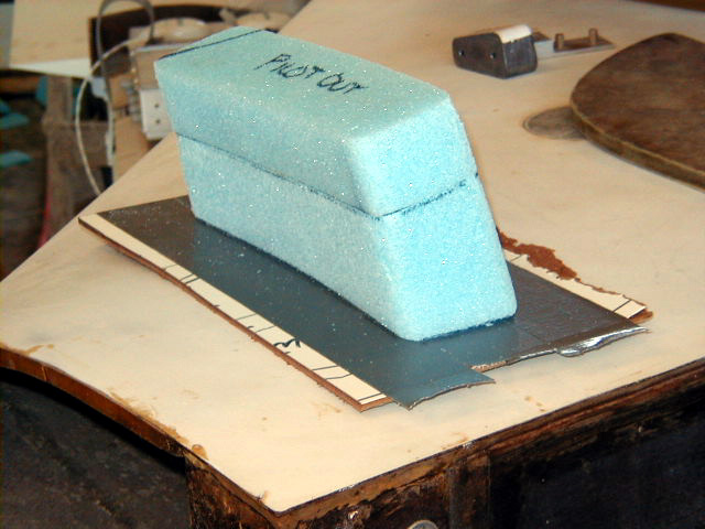
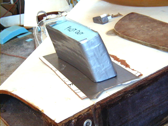
| Ducts clecoed into position to front half plenum, front view. | Ducts clecoed into position to front half plenum, view from inside. | Building slip joints for communication from NACA scoops on roof of fuselage to molded ducts seen above. Blue foam is shaped to size. | Duct tape laid over the foam. Fiberglass will be laid up on outside and onto base to make flange. After curing, the foam and tape is removed leaving a short duct. These are attached to the firewall at the NACA inlet throats. The short duct fits inside the molded ducts seen above. They are not secured to one another, thus preventing vibrations from being passed directly to the firewall structure. The setup can be seen in the first few photos of this section of N99KT's cooling system. |
|
|
|
|
|
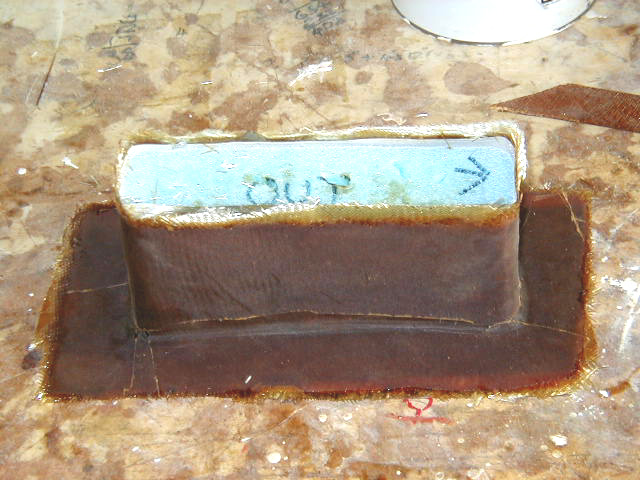
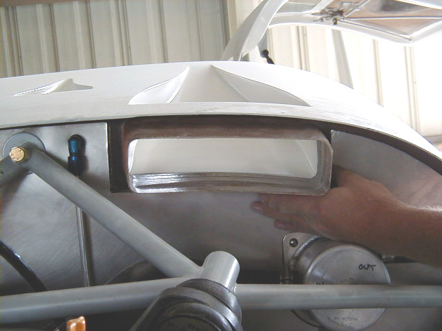
| Slip joint after glassing. | I'm meeeelting!!!! Acetone used to melt blue foam inside now cured part. | Slip joint cleaned up. | Slip joint held in position at inlet of NACA scoop. Molded plenum ducts slide over this part. |
 Comments, questions, and suggestions are welcome! email: rich@rguerra.com
This page visited times.