


The photos below are arranged chronologically and illustrate the process of building the NACA Scoops, roof reinforcement modifications, and other final structure.
Velocity, Inc. now recommends using National Advisory Committee for Aeronautics (NACA) style flush (or "submerged") air intake scoops for engine cooling rather than under wing "armpit" scoops. This greatly decreases drag. The new scoops are located on the roof of the fuselage. The factory recommended scoops will be somewhat modified in shape in N724X. The Hangar 18 modified NACA scoops are derived directly from declassified National Advisory Committee for Aeronautics (NACA) reports on flush inlets. The basics on the NACA ducts are: 1) intake throat aspect ratio between
3:1 and 5:1 (L X W, these are 9" X 2.5", or almost 4:1). 2) ramp angle is
optimum at 7 degrees, so given the size of the inlet throat plus the aft edge of
the inlet being most effective with a 1/4" radius, this calls for a 1/2" thick top
aft inlet "roof". A ramp angle of 7 degrees
and a depth of 3" determines the length based on the formulae. The length of the external opening of the NACA scoops is 24". 3) The S-curve of the walls was derived from a NACA formula described on the NACA Flush Inlet report web page. A table is provided giving the coordinates for laying out the planform of a "curved divergence" NACA flush inlet. Without the right curve, the air will not spill into the low-pressure area of the inlet with the correct vortex flow to attach it to the inlet sides and bottom and thereby direct air down the ducts into the intake
feeds. The relationships between size and shape detailed above were meant to achieve an optimal compromise between ample cooling and drawing too much air which would result in a drag penalty. The published nominal figures were applied to the Velocity airframe. These modified scoops have been found extremely effective in previously built Hangar 18 Velocity XL RG's.
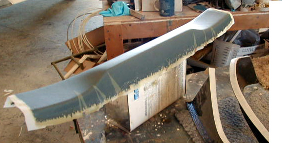
The switch panel is modified and stiffened in the sequence below to transform it into a structural component of an overhead "roll bar" structure. Basically, the trim piece is stiffened with carbon fiberglass and, when it is set in place between the forward carbon beams and bonded to them, it becomes the top portion of a complete arch to complement the one at the aft edge of the doors. The previously enhanced carbon reinforced roof seen in the Upper Fuselage section and here bridges the gap between the fore and aft carbon beams to form an overhead "roll bar" structure (or perhaps more accurately, a "canopy") to stiffen the fuselage top at the doors and protect the occupants.
The switch panel is modified as follows:
1) inside sanded well then 1 layer of 15.9oz carbon Bid on a 0/90 axis, purposely left to stick straight up from "walls" of switch panel, rather than trying to bend them over onto the flange.
2) outside flanges removed and sanded well, then 1 layer of 5.7oz carbon
Bid on a +45/-45 applied on the outside, extending down to the inner
cabin, thus deepening the part.
3) the part is trimmed to fit and installed with 2 layers 3" wide
coarse BID all around perimeters.
4) A hole will be cut in the aft face of the panel just a little bigger than the electrical switch panel when it is available (making sure there is adequate clearance to the roof for the equipment installed!) A release-treated 4 BID layup will be made on a flat surface and for a piece big enough to create a flange that glues inside the switch panel which receives the panel when the time comes to install it. This method also provides a way to hide the upholstery edges where the panel mounts, as it's recessed, and the panel will be easy to remove and maintain, if enough wire is left to pull it out a little ways.
Also of note are the wire conduits traveling inside the front carbon beams. The switch panel will require quite a few wires running to and fro. A conduit in both of the
front beams will make the job of wiring much easier. The material is $.20/ft
1/2"OD poly tubing from ACE hardware. The conduit exits at bottom front of each beam.
Installation of nylaflow rudder cable conduits is illustrated.
The installation of the wall forming the forward border of the baggage area in the strakes is illustrated.
The preparation and installation of the battery tray and the nose gear guides are illustrated.
The nose section of the fuselage is permanently bonded to the remainder of the fuselage.
Hangar 18 specially made pre-molded carbon reinforced strake tips are installed overlapping the doors.
Click on thumbnails to view larger versions of the pics!
2015 cheap best swiss rolex,panerai,iwc,hublot,tag heuer,breitling,patek philippe,omega Constellation watches,omega DeVille watches,omega Seamaster replica,top quality bvlgari,cartier,chopard,corum,franck muller,longines,tissot,u-boat,ulysse nardin,versace,glashutte,graham jaeger lecoutre.we also keep these watches entire brands:audemars piguet,breguet.
|
|
|
|
|
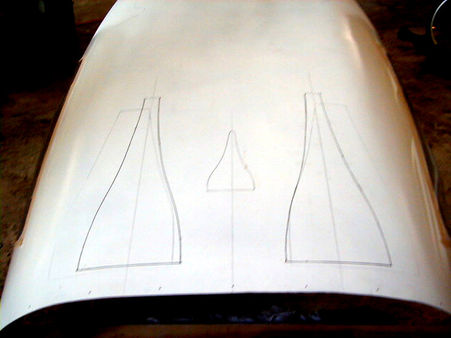
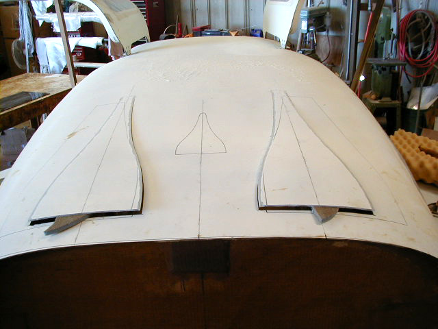
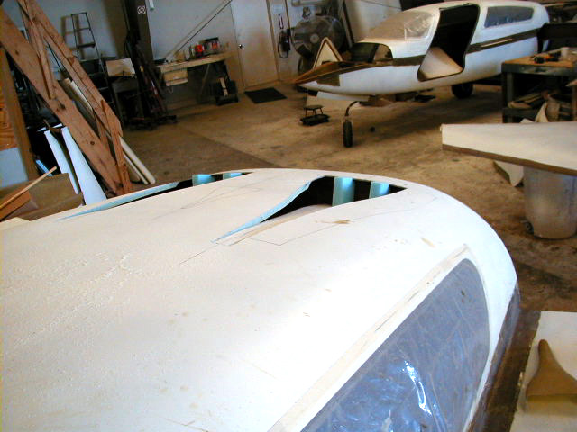
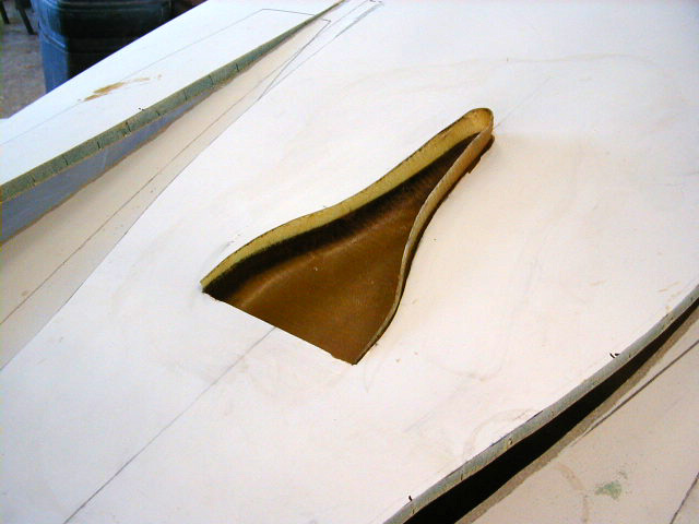
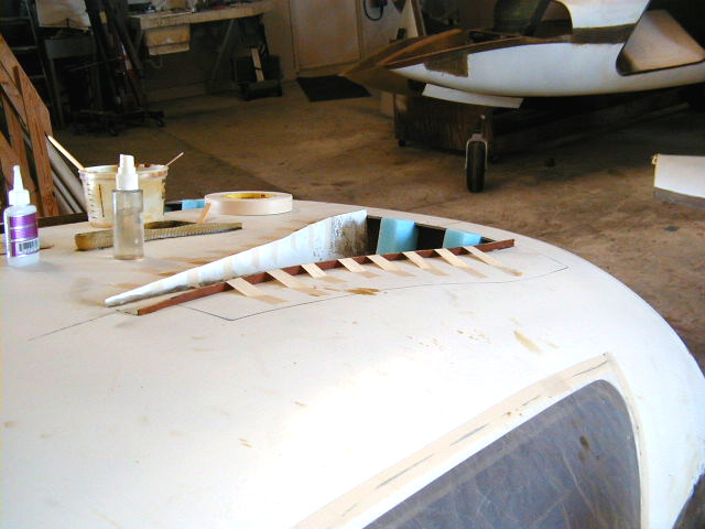
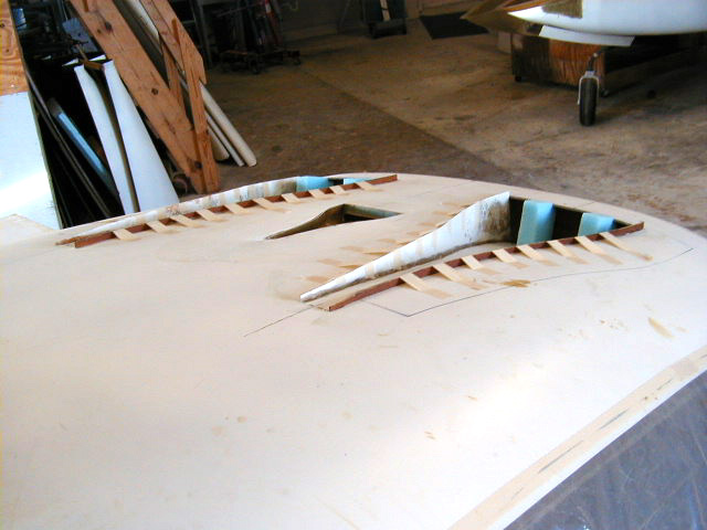
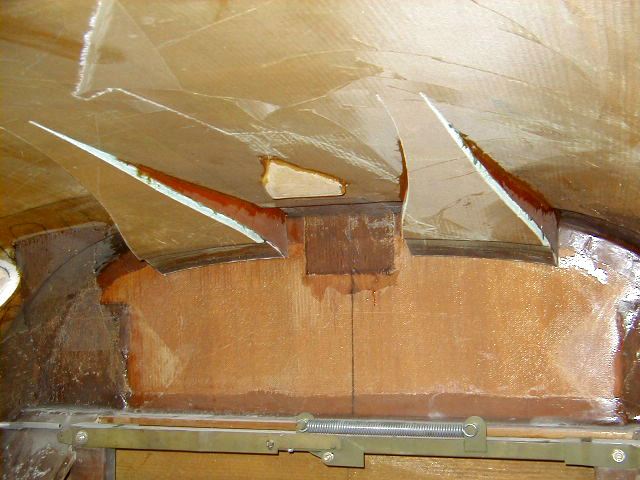
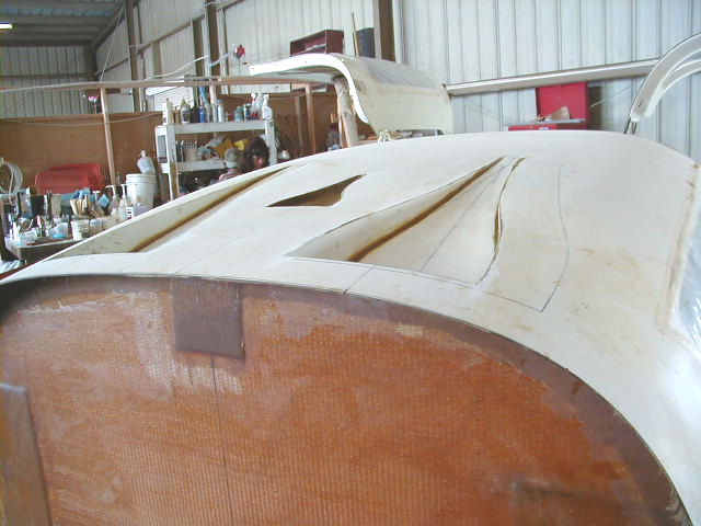
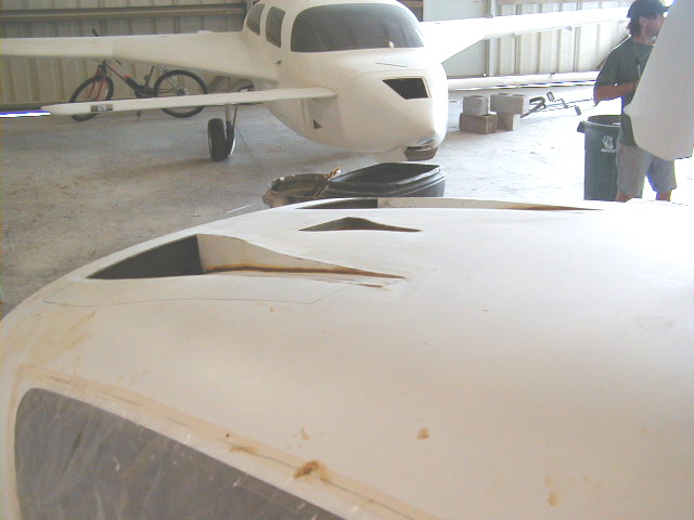
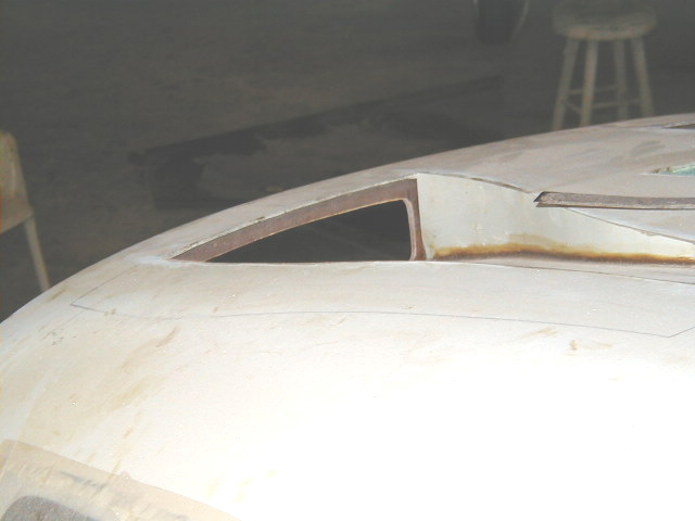
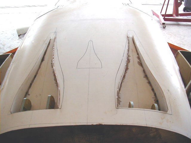
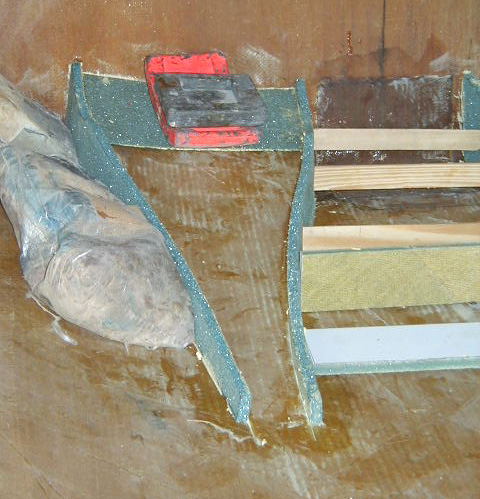
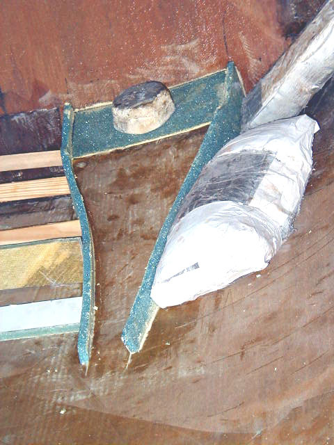
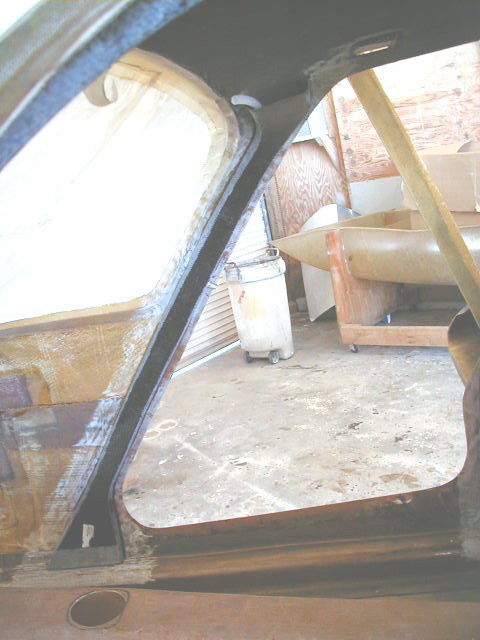
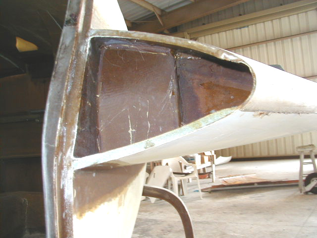
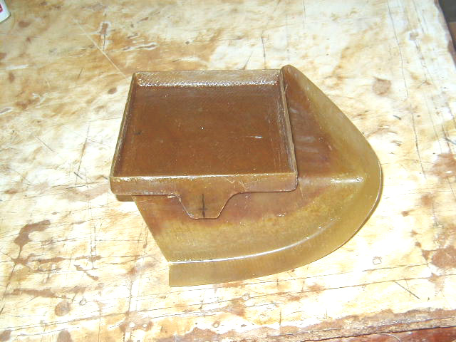
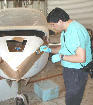
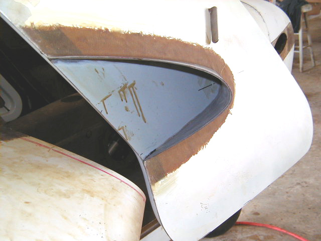
| Hangar 18 modified NACA scoops. The darker outlines delineate the position and shape of modified NACA scoops in the roof of the upper fuselage. Compare with lighter lines which are the factory inscribed scoop outlines. How are they different? See discussion above for details on the modifications. | NACA scoops incised leaving the front edge in place for use as a "hinge point" to bend the cutout downwards to form the "floor" of the inlet. Primer is removed along the edges of the cutout to facilitate attaching the side walls of the inlet. Again, note modified shape and dimensions of these scoops. | The cutout from the roof of the fuselage forms the "floor" of the NACA inlet. The newly freed aft ends of the cutout are pushed downward into the fuselage and wedged to the proper depth. | Cabin air intake premolded part placed in position after cutting appropriate hole in fuselage. The "floor" of the scoop is placed at the correct angle. The protruding portions of the part will ultimately be removed flush to surface of roof. |
|
|
|
|
|
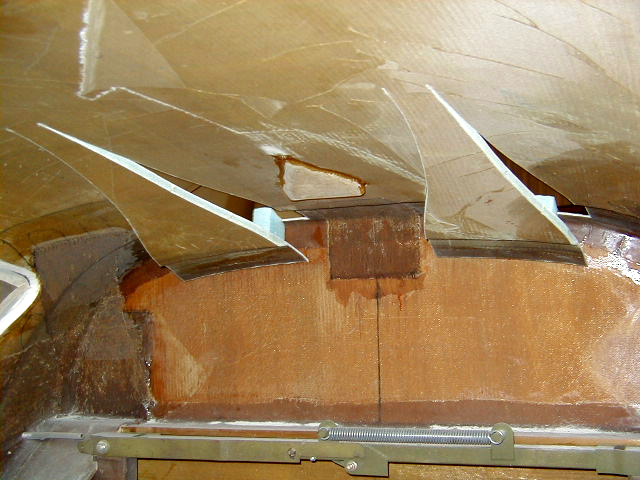
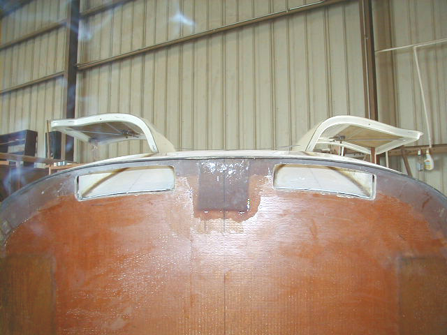
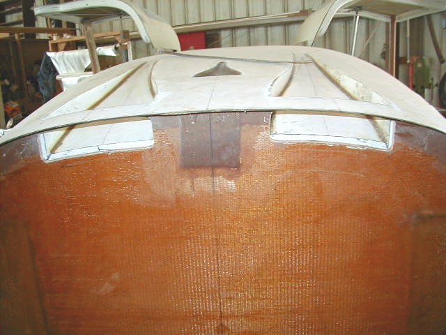
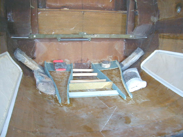
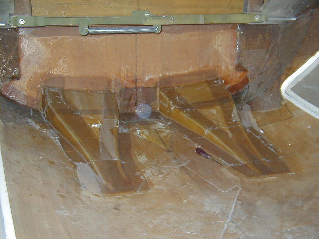
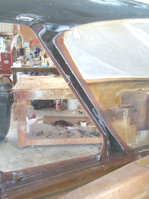
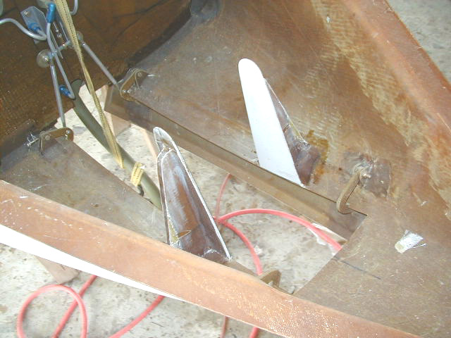
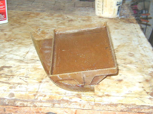
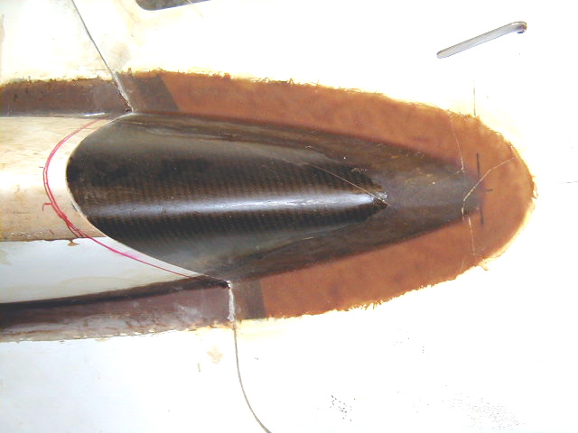
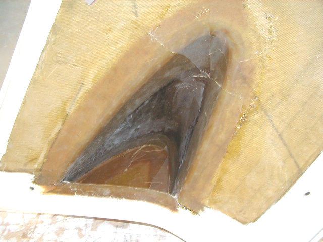
| Inside view of NACA inlets wedged to appropriate depth. Note NACA inlet for cabin fresh air plenum (a pre-molded part) installed in between the two larger engine air intakes. | Side walls installed in scoop. "Curved divergence" shape of the NACA submerged inlet easily seen here. | Another view of the side walls of the inlet installed. The protruding edges of the side walls will be removed flush to the fuselage roof leaving a sharp, vertical transition from roof to scoop. In contrast, the aft edge of the inlet will ultimately be shaped as a blunt leading edge type shape 1/2" thick. Air passing over the sharp edges of the inlet spills inward and curls inward back towards the wall. This creates a vortex clinging to the wall on each side which draws air down and directs flow along the floor of the intake and ultimately, through the aft opening to the engine compartment. | Walls of both NACA inlets installed. Protruding edges of pre-molded fresh air NACA intake removed flush to fuselage roof. |
|
|
|
|
|
| Inside view of NACA ducts with side walls attached. Cabin air intake inlet alo seen in center. | A small radius formed at bottom edges of inlet "ramp". | Another view of the the small radius formed at bottom edges of inlet "ramp". | Holes cut in firewall for NACA inlets. |
|
|
|
|
|
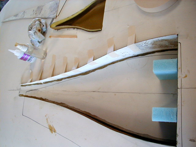
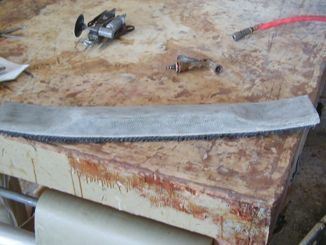
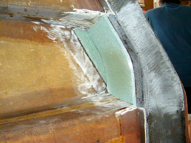
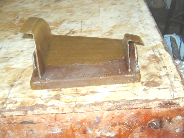
| Another view of hole in firewall forming the aft portion of the inlet. | Pieces inserted to form the extensions of the NACA inlet ramps through the firewall. A "slip joint" will ultimately be installed here to minimize transmission of vibrations to the inlet structure. | By way of comparison, this is a photo of the NACA inlets installed on Dan Fast's Standard Velocity. Note the somewhat smaller size. Like the inlet scoops seen on my XL, they have been adjusted to provide an appropriate amount of air flow for the smaller powerplant to be installed. They are tailored to size and shape based on the same NACA formulae used to design my XL's scoops. Again, note differences in size and shape from factory scoops. | Final assembly of NACA inlets. Foam used to increase bulk of sides of ducts which ultimately will be glassed over. |
|
|
|
|
|
| Closeup of pilot side NACA inlet. | Closeup of copilot side NACA inlet. | Weights used to hold foam in place after epoxied into position. | NACA inlets glassed over after shaving the foam to appropriate shape. NACA inlets completed! |
|
|
|
|
|
| Nylaflow tubing serves as conduit for rudder cables. It is installed by laying up fine BID fiberglass over the tubing as it courses down the length of the fuselage along the wire ducts. The front portion of the rudder cable conduit is seen here. | The aft portion of the rudder cable conduit is seen here. Pilot-side strake baggage area is seen upper center of photo. | The factory supplied molded switch panel is modified from a trim piece to a structural support. Here the panel is sanded and flanges removed. The piece is modified to be taller to match the size of the carbon beams to which it will later be bonded. This also improves access for wiring and fitting the switch panel. | 15.7oz/yd of carbon fiber is laid up on a 0/90 axis on the inside of the overhead switch panel ... |
|
|
|
|
|
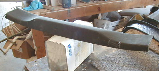
| ... and on a +45/-45 axis on the outside of the panel. | View of the fully-modified switch panel, now stiffened considerably with the carbon fiberglass. It is now sized to match the forward pair of carbon beams. | Wire conduit opening in the front carbon beam. | Wire duct installed in forward carbon beam. 1/2" poly tubing glassed in place with a layer of fione BID. |
|
|
|
|
|
| Front carbon beam fitted in place. Note wire conduit dangling out top end. Adjacent fiberglass sanded in preparation for layups to bind the beam to the fuselage. | Front carbon beam glassed in. Wire conduit seen at top center of photo. | Rear carbon beam fitted into place just aft of door. | Rear carbon beam glassed in place. |
|
|
|
|
|
| Foam fitted to form front wall of baggage area in strake. | The aft face of the front of baggage area in strake now glassed over. | Forward face of baggage strake glassed over. | Nose gear guides now installed. |
|
|
|
|
|
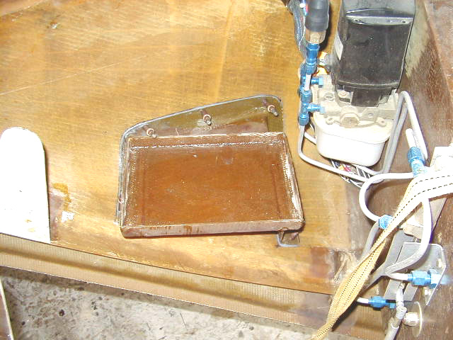
| Battery tray prepared for installation | Further battery tray prep. The size and shape of the tray is tailored to the battery to be used. | Another view of battery tray preparation. | Battery tray installed |
|
|
|
|
|
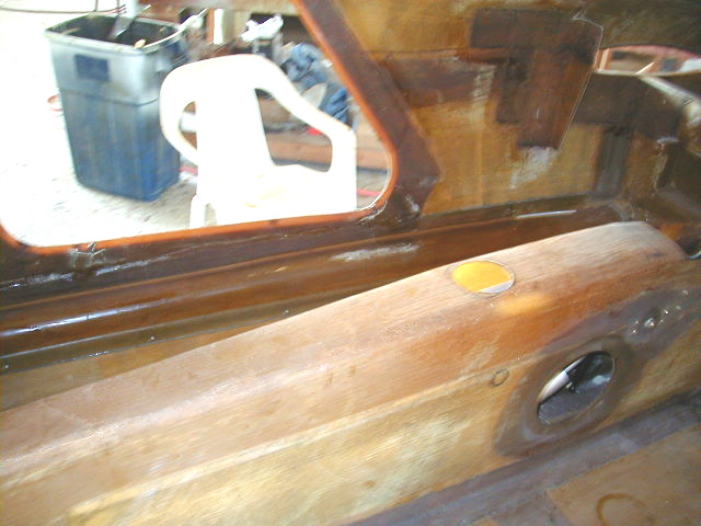
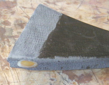
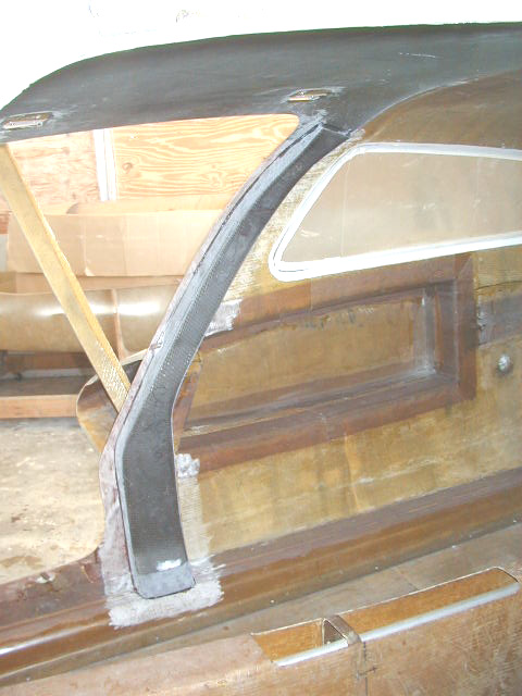
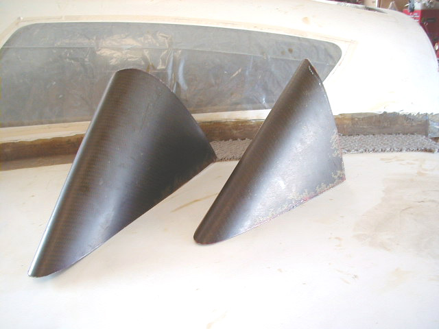
| The nose section of the fuselage is permanaently attached with layups of BID tape on both inside and outside. Peel ply being applied here. | Another Hangar 18 special: molded carbon reinforced strake leading tips. The plans call for use of the previously removed tips of the strakes to be bonded to the doors. The disadvantage is that the space inside this tip is decreased since there is foam core forming the structure. The leading tips shown here are specially molded parts that are formed out of layers carbon fiber, UNI and BID. They are light and extremely strong. | A pre-molded Hangar 18 strake leading tip attached to door. The inside surface of the door will be cut out leaving the space inside available. The piece is strong enough to stiffen up the door at this point. | View of an installed leading edge piece demonstrating the thickness of the molded part as opposed to the foam core part. |
|
|
|
||
| Inside of strake tip after cutting into door and glassing over. | Aft face of strake tip with space now enclosed by a bulkhead. |
 Comments, questions, and suggestions are welcome! email: rich@rguerra.com
This page visited times.