


.jpg)


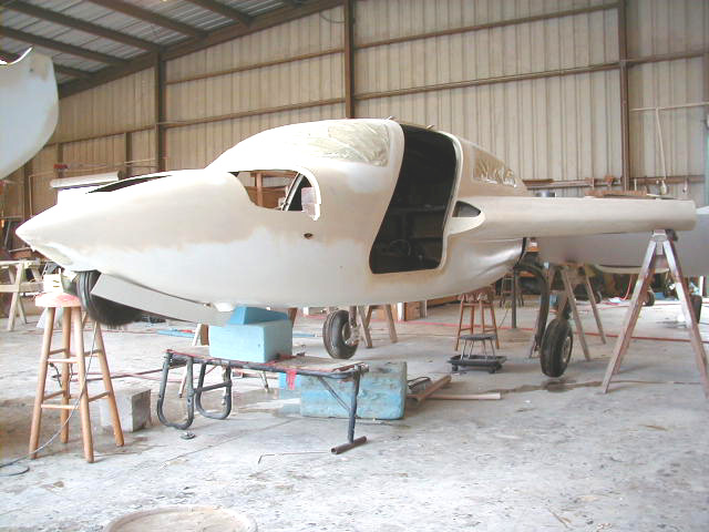
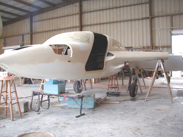
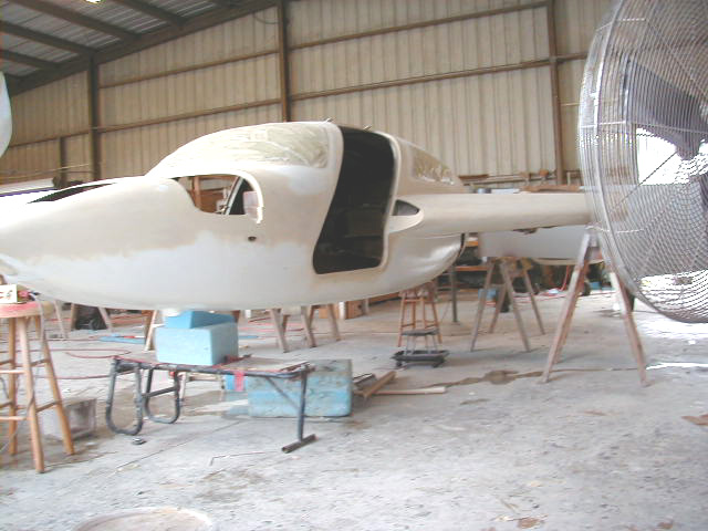
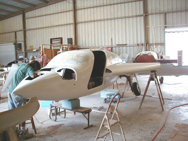
Details of construction of various miscellaneous systems starting about 9/3/01. Hydraulic gear system, overhead air vents, Vance Atkinson sight gauges, N724X in final primer!!!, brakes, seat belt hard points, hidden tie downs, gear control box, closeout bulkhead for nose section of fuselage, pics of flush window installation, gear doors, oil cooler cavity closeout, fuel tank and line testing, cabin heating system.
|
|
|
|
|
| Nosegear and doors cycling! | Up she goes! | Doors closed! | All together now! |
|
|
|
|
|
| Gear UP!! | Pitot tube mount. Heated pitot tube AN5812-12 used. | Overhead air vents in place. Large sized vents from Chief Aircraft used (Wemac vents 1 1/4" outlet, WEM 2373-1) | Rear seat bottoms. |
|
|
|
|
|
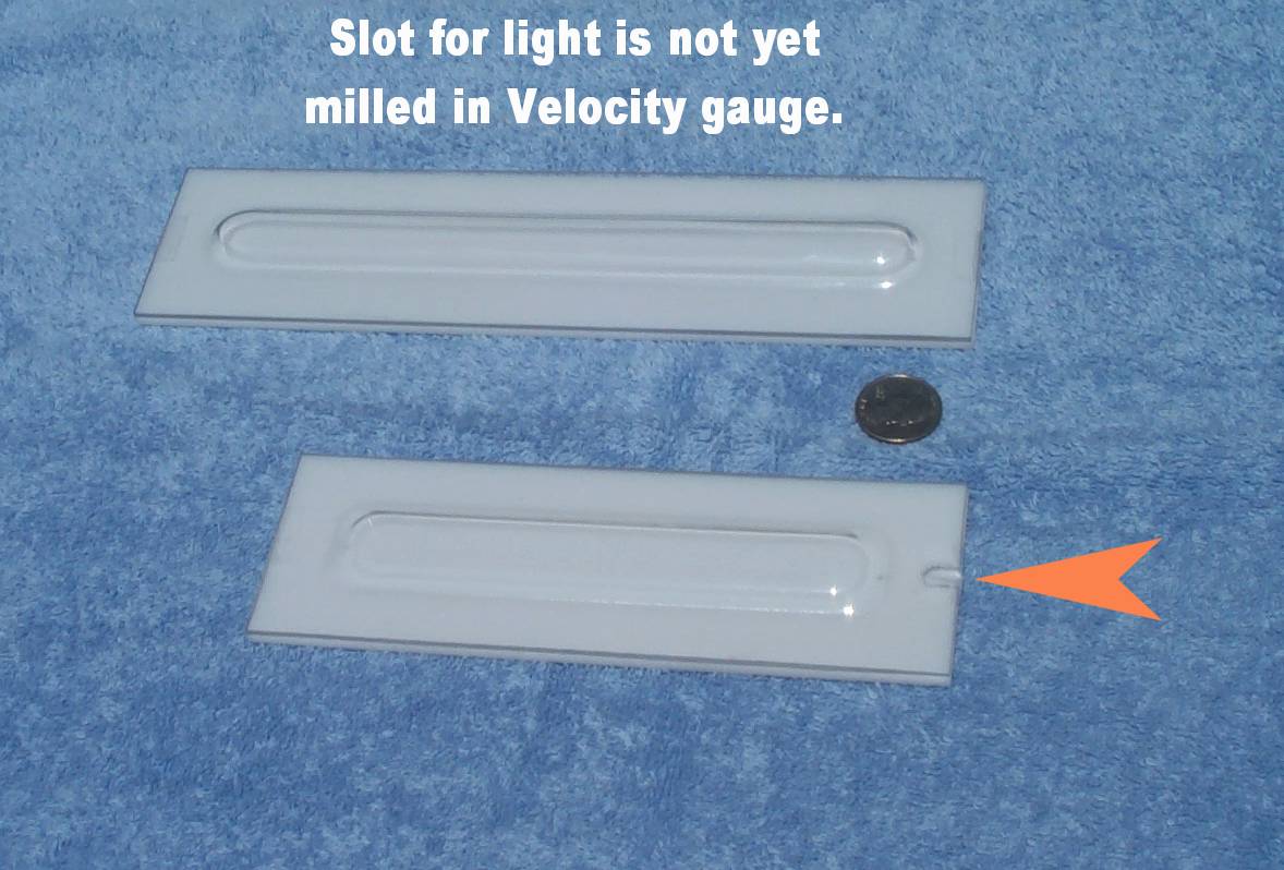
| Rear seat bottoms. | Reworked seat hard points to accomodate updated sliding seat rails. | Here is a photo of the NEW, Velocity specific, fuel sight gauges sent to me by Vance Atkinson. Many Long EZ builders have spoken highly of these and a number of Velocity builders have used these with good result. Highly recommended! They can be obtained directly from Vance who can contacted via email at nostromo56@attbi.com . | |
|
|
|
|
|
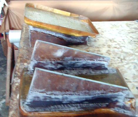
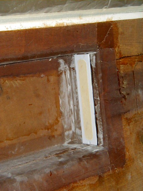
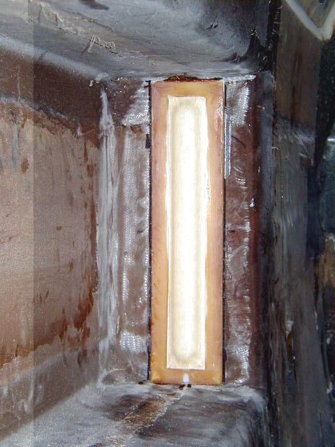
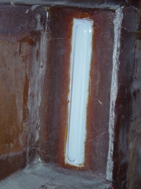
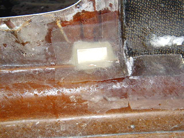
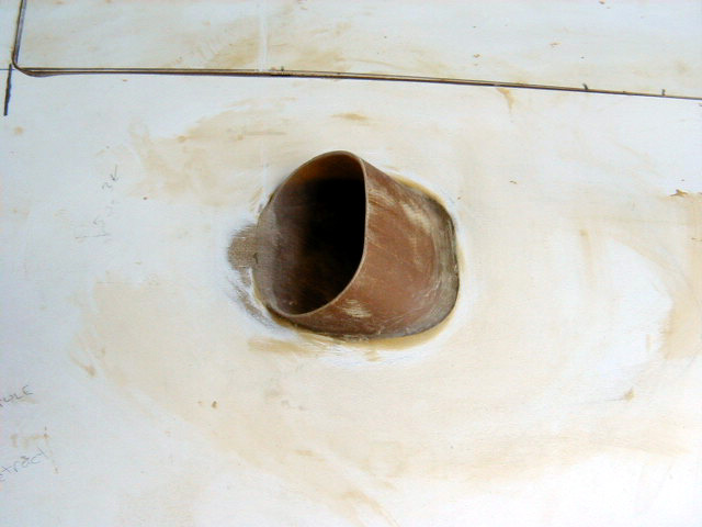
| Vance Atkinson Velocity Sight Gauges prepped for installation. | A 3/4" circle of the inner skin of the baggage compartment was removed taking care to not damage the upper or lower skins of the strake. The foam is dremeled out then back-filled with cabo. After cure and clean-up,the white backing plate is bonded to the bulkhead. The 1/16" holes that you see on the gauges are used as guides to drill into the tank carefully, through the cabo plugs. Hardly any trash goes into the tank, as the spiral flutes of the drill bit pull the shavings out of the hole being drilled. Then the clear cover is bonded on and glassed over. There you have it! | Back plate of gauges bonded in place. | Sight gauge installed. Note slot for LED at bottom of gauge. |
|
|
|
|
|
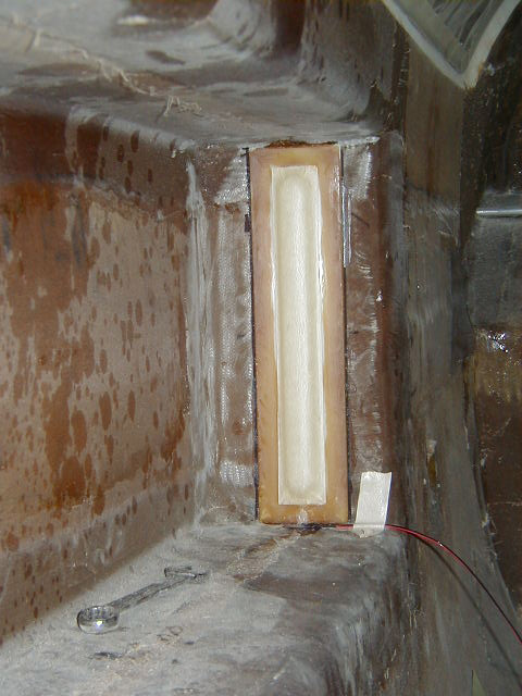
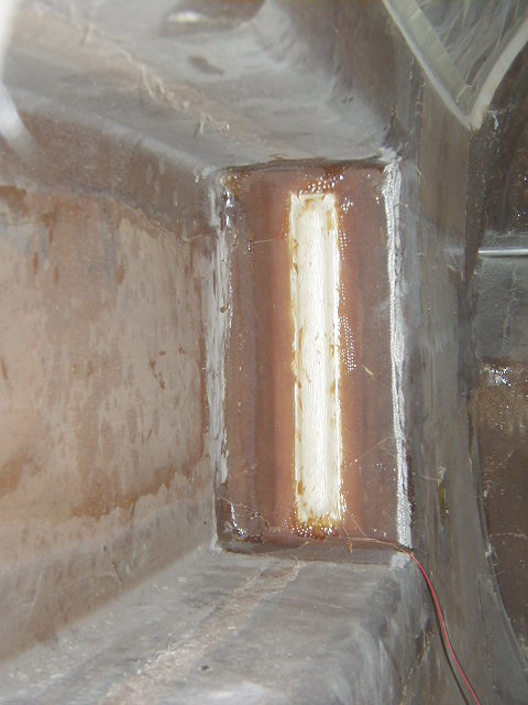
| Sight gauge LED installed. | Sight gauge glassed in and completed. | Vance Atkinson sight gauges, final. HIGHLY RECOMMENDED!! Contact Vance Atkinson directly to order. You can see wires for LED in lower corner. | Final white primer shot on the plane!! |
|
|
|
|
|
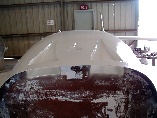
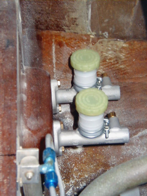
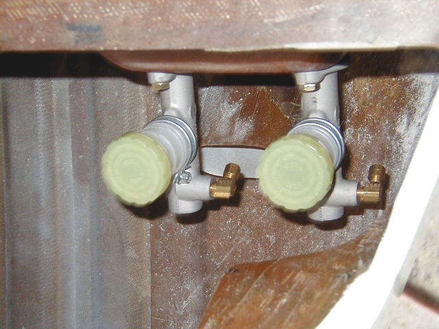
| Beautiful NACA inlets and upper fuselage in final primer! | Brake masters fitted on canard bulkhead. | Another view of brake master cylinders. | |
|
|
|
|
|
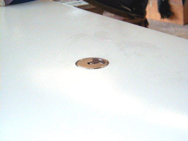
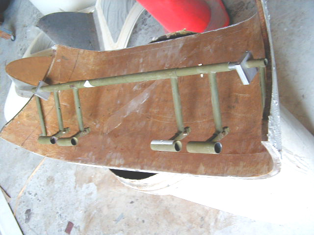
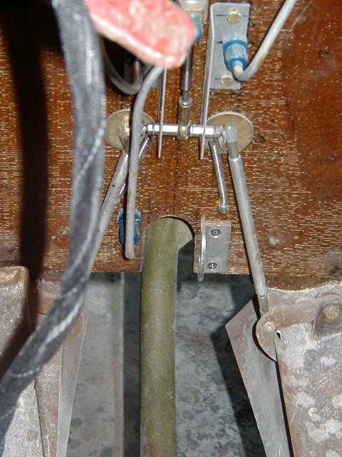
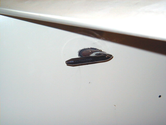
| Locking fuel cap in place, flush fitted. | Rudder pedal assembly (displayed on underside of canard cover) | Front seat lap belt hard point, inboard side. | Front seat lap belt hard point, outboard side. Note carbon beam directly aft of the hard point. |
|
|
|
|
|
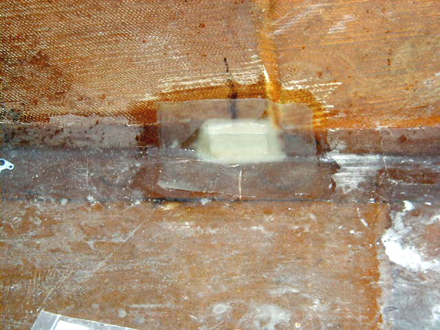
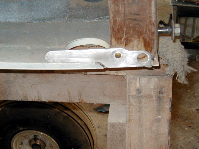
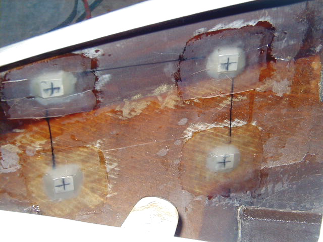
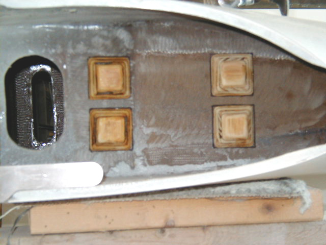
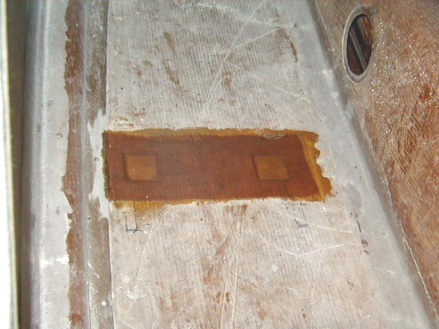
| Rear seat bottom mounts. The angles are not mounted through just the foam core as per plans. There is a 2" X 2" slug of milled fiber that was pushed into a cavity cut in the core, for maximum sturdiness. | Rear seat lap belt hard points. | Large and small main gear doors now in place. | Hangar 18 special: hidden tie down points. Attached to center spar, they swivel down for use ... |
|
|
|
|
|
| And are tucked in for flight. | Nose tie down point just inside nose gear door. | Pilot door now latched into place. | Putting in mounting points for the gear control box in the nose section of the fuselage. This is view through hatch in nose section. Nosewheel guide seen in lower center of photo. The battery tray is seen at the lower right. |
|
|
|
|
|
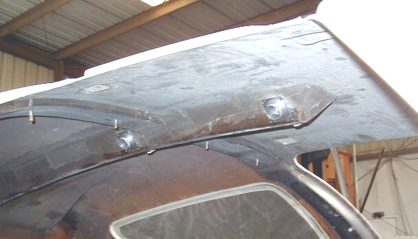
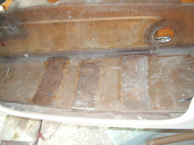
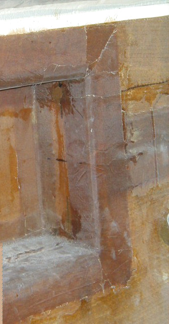
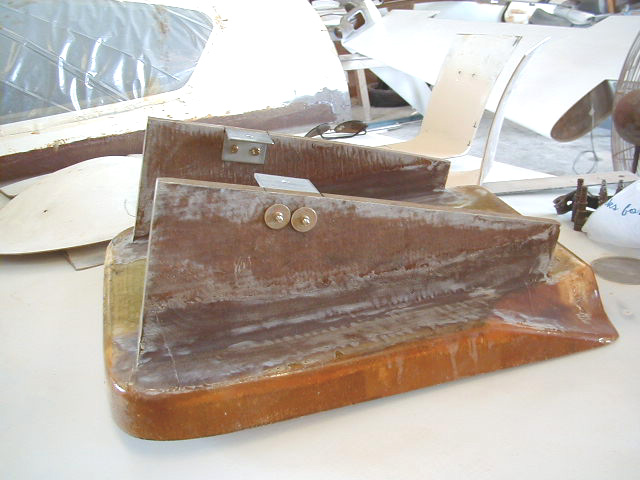
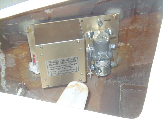
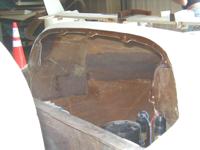
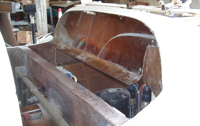
| Points glassed over. | Hydraulic gear control box mounted. | A Hangar 18 refinement: A nose section closeout bulkhead. Fiberglass is laid up on a piece of glass treated with release agent and then trimmed to fit in the opening forward of the canard. The fiberglass sheet is held in position with tape. The top of the rear of the bulkhead is covered over with duct tape. and a flange is laid up behind attached to the upper surface inside the nose section. A section of the leading edge undersurface of the canard is covered with duct tape and fiberglass laid up attaching to the rear lower edge of the bulkhead sweeping under the canard. This forms a lip along the lower edge of the bulkhead. This shape is seen in the following photos. | Bulkhead showing lip to curve under the canard. |
|
|
|
|
|
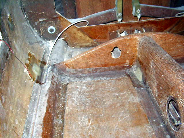
| View of the surface of the closeout bulkhead facing the forward nose section. | View from the nosegear well looking upwards toward the rear of the nose section of the fuselage. The white undersurface of the canard is seen just above the canard bulkhead, battery tray seen left corner, brake master cylinder on right. You can see duct tape still in place that allowed layup to form the undersurface flange of the closeout bulkhead. Air entering into this section throught the nosegear doors will tend to push the closeout bulkhead tightter against the canrd, thus enhancing the seal and preventing leakage of water and cold air into the space behind the instrument panel and the cabin. | Flanges for the closeout bulkhead trimmed to shape. | Closeout bulkhead completed and in place. The shiny surface reflects the opposite side of the canard opening. You can see how the canard will drop into place and snug up against the lip running along the lower edge of the bulkhead. This system has worked well on other Velocity XL's and keeps the back of the panel nice and dry. |
|
|
|
|
|
| Wood mounting points for Whelen Strobe control box on the outer bulkhead of the strake. These are applied to prevent mounting screws from penetrating the fuel cell bulkhead! | Strobe box mounting points glassed in. | Pitot tube mounted. | Rear seat hard points. |
|
|
|
|
|
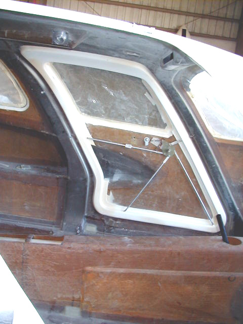
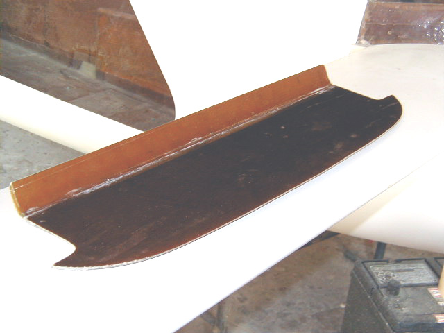
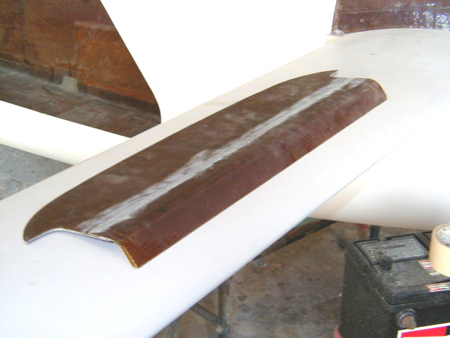
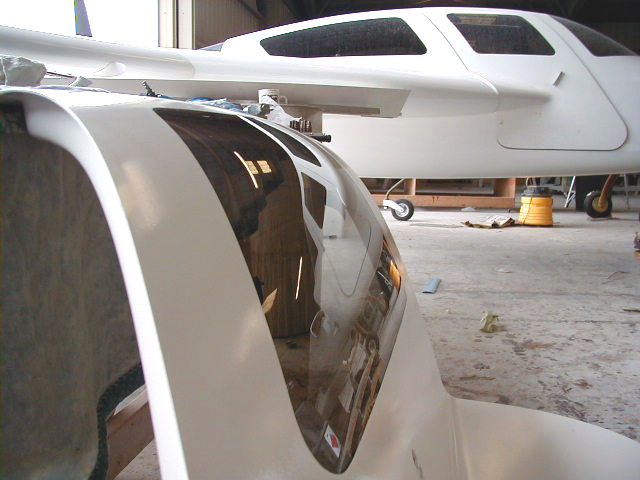
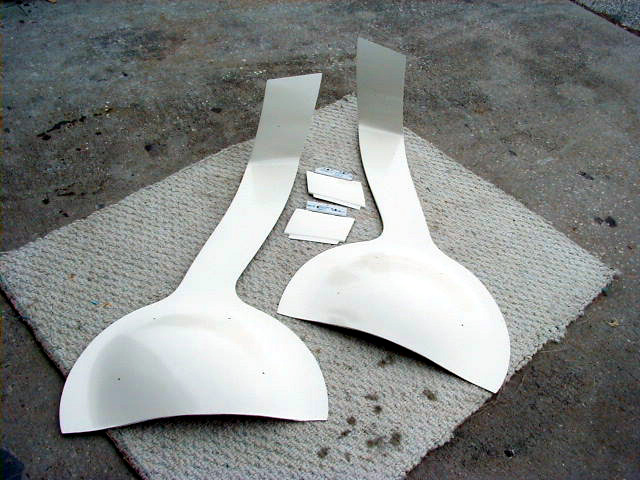
| Final finish work around windows illustrating flush installation. Ken Tonyman's beautiful XL, N99KT in background. | Large and small main gear doors in final white primer. | Pilot door in final white primer. | Rib constructed to seal the oil cooler cavity in the wing root. |
|
|
|
|
|
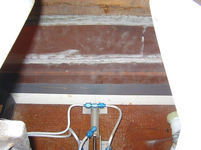
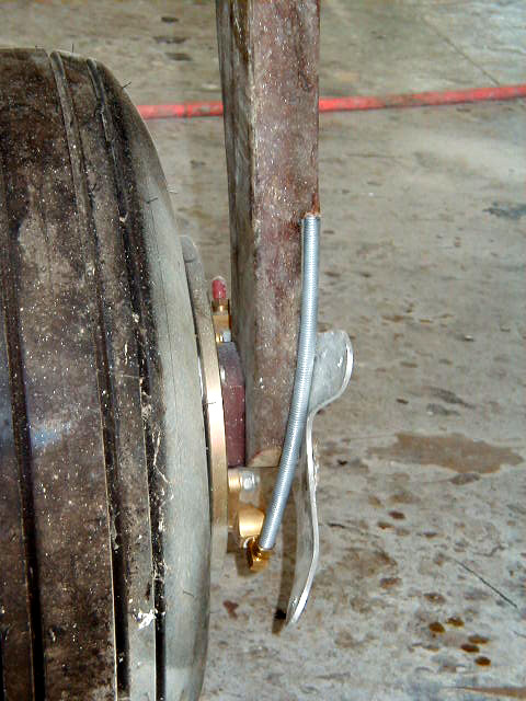
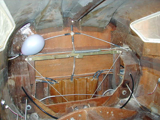
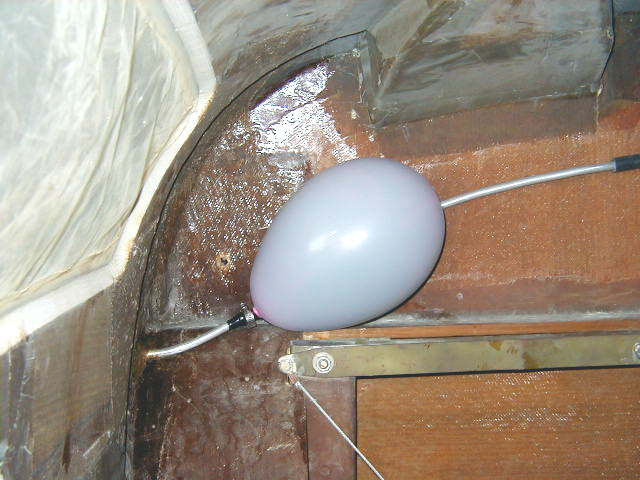
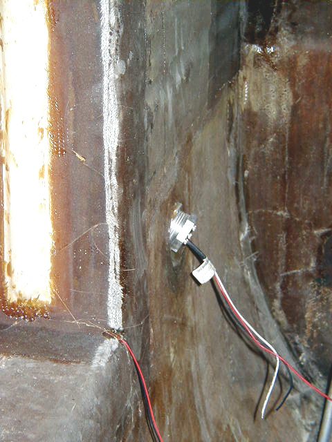
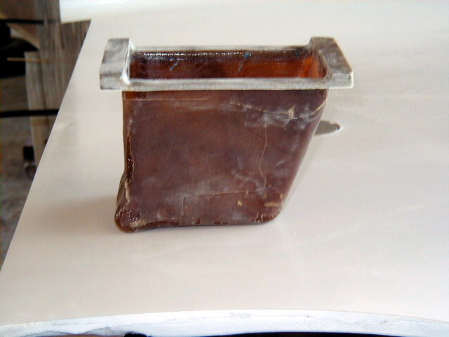
| A screen door hinge from Ace hardware is cut to length and slid over the exposed brake line. This protects the line from debris that might be kicked up and damage the line. | Fuel line and tank vent plumbing. Sump tank seen in lower center of photo. The balloon is not a leftover from the last hangar dance, but a way to test for leaks in the tanks or the lines. This balloon stayed inflated! | Testing the fuel cell - passed! | Vision fuel sender unit in place. Vance's sight gauge can be seen at left. |
|
|
|
|
|
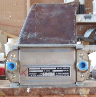
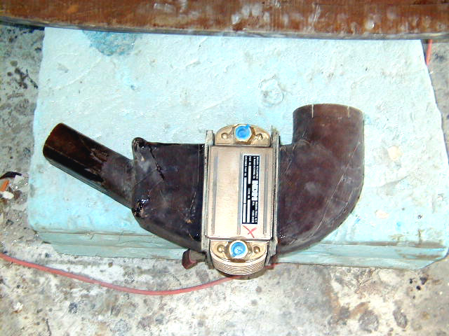
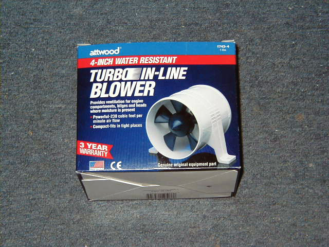
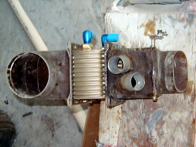
| Details of cabin heat/defrost system. Cabin heat diverter box seen here. Air will be pulled from the cabin from behind the instrument panel through the canard closeout bulkhead seen above and passed through a nose-mounted oil cooler. | Oil cooler in place to show how the part attaches. | Fan to cooler duct. | Fan mounting flange on canard closeout bulkhead. |
|
|
|
|
|
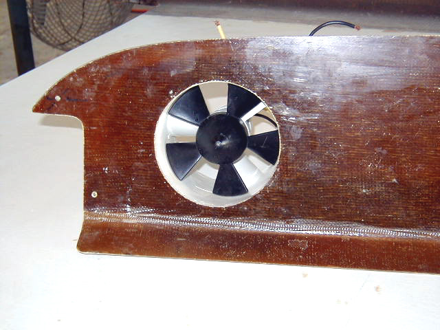
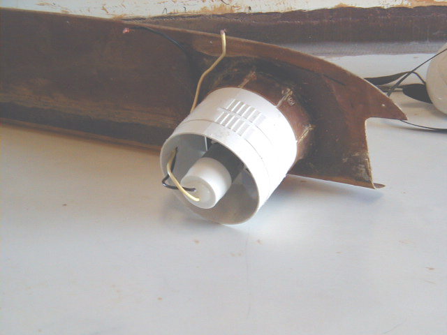
| A small marine bilge fan in place in the canard closeout bulkhead. | Rear view of fan. | Ductwork assembled showing path from bulkhead through fan to oil cooler. | |
|
|
|
|
|
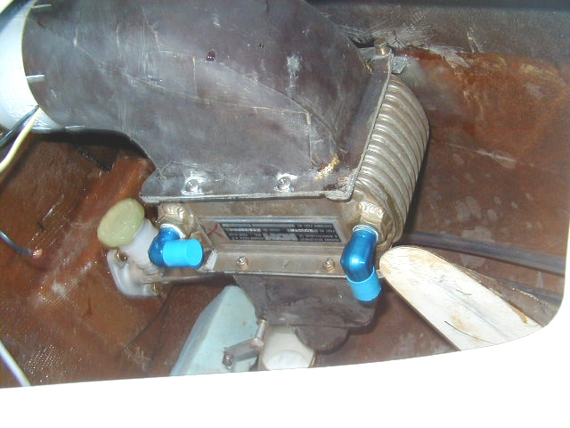
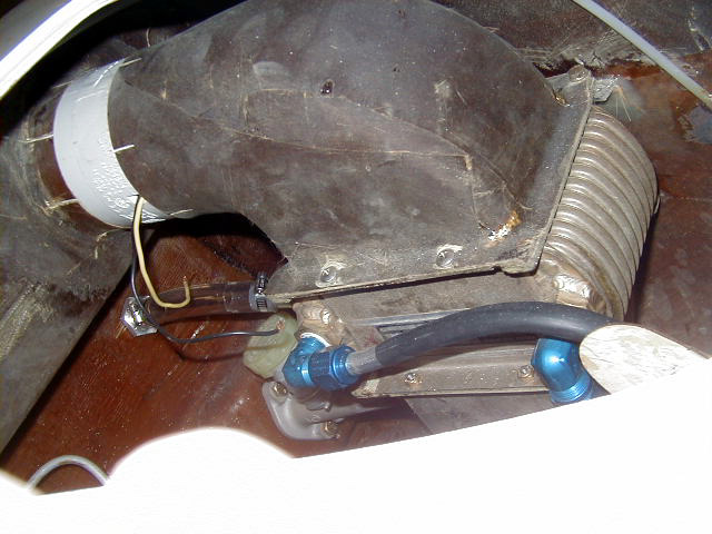
| Bilge blower. Flanges pictured are removed for installation. | Cabin heat assembly. | Oil cooler and heating ducting installed in nose section. | |
|
|
|
|
|
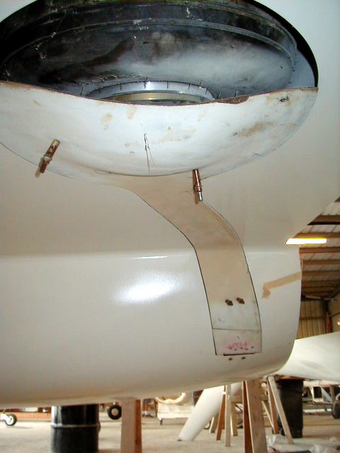
| Cabin heater/oil cooler mounted. | Cabin heater outlet protruding from lower surface of fuselage. | Another view of cabin heater outlet. |
 Comments, questions, and suggestions are welcome! email: rich@rguerra.com
This page visited times.