


I find one of the greatest gifts of flight is the unique perspective on the world from above. Words alone often cannot convey the spectacular beauty we as pilots are privleged to witness. In hopes of sharing some of these sights, I've decided to install cameras in the lower winglet portion of the wings. Details of the installation will be seen here in the coming weeks. I've chosen a MVC6470 Hi-Res Color CCD tube camera from MicroVideo. I plan on attaching the camera to a small servo made from an electric side view mirror from a 1981 Datsun 200SX. This will allow some panning ability and hopefully will allow shots of the plane itself in flight from the vantage point of the wingtip in addition to terrain passing below and the view toward the horizon. The camera output is suitable for recording by a standard camcorder or display on a small TV monitor. I plan on having the output jacks in place in the instrument panel in addition to the panning control. The cover for the camera is a 4 inch diameter acrylic dome made by Falconar Avia, Inc.. They specialize in larger canopies for aircraft but were able to very handily make the small domes for me. The domes are very clear and distortion free. Now that they have the tooling, similar domes can be manufactured.
After some deliberation regarding angles of view, we've been able to proceed rapidly. The build process is illustrated below. SEE PART II FOR THE REMAINING CONSTRUCTION!!
Click on thumbnails to view larger versions of the pics!
|
|
|
|
|
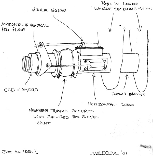
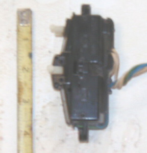
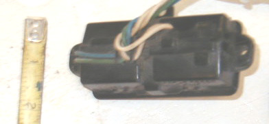
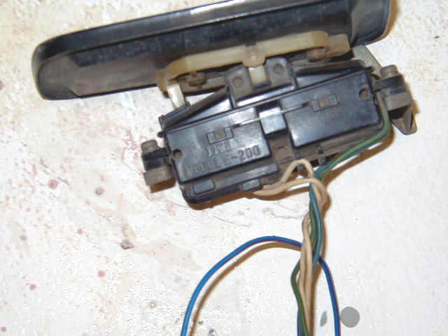
| Proposed mechanism to allow for adjusting angle of camera within winglet bottom. This arrangement has been refined somewhat currently. A small servo unit from an electric side view mirror measuring 2 inches by 3 inches will be used. We will post more drawings and photos soon. | This is a somewhat blurry image of the servo unit from the electric side view mirror, provided primarily to give a sense of size. The white plastic fittings in the center and on the upper end of the unit attach to a plate on which the mirror resides. The center fitting swivels side to side whereas the upper fitting moves in and out. This results in change of angle of the mirror. We plan on attaching the camera to the mirror platform to obtain the same motions. | Back view of the servo unit showing its width. This will make it suitable to fit inside the hollow lower winglet. | Servo motor and mirror assembly showing the interaction between the servo actuators and the platform which allows for the motion of the mirror. The large mirror platform will be removed and the camera attached to the white plastic fitting connected to the servo actuators. |
|
|
|
|
|
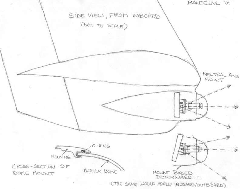
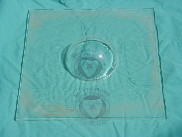
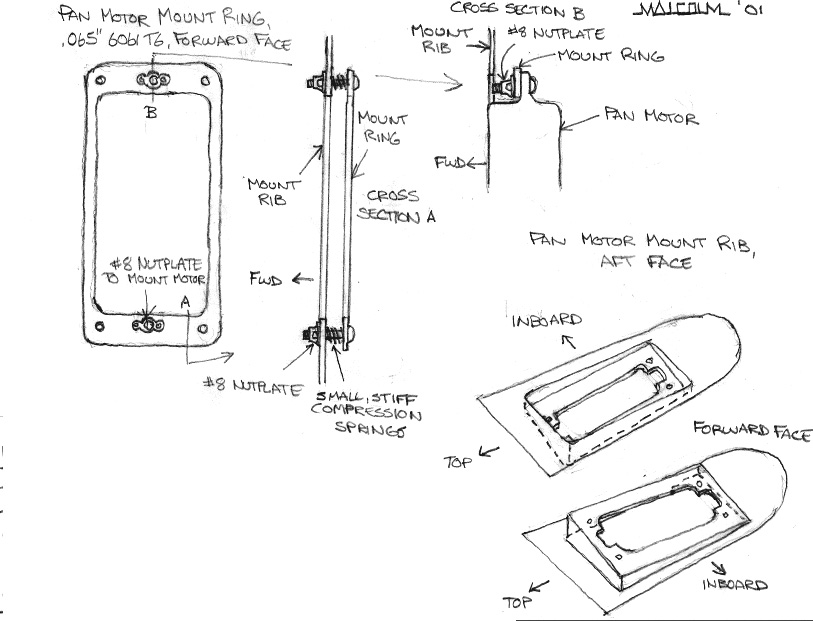
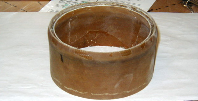
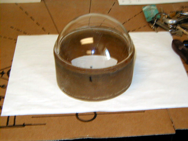
| Servo motor control switch which controls the direction in which the platform moves. Ultimately, we will most likely switch to a coolie hat type switch to blend in better in the panel. | PRELIMINARY SKETCH of wing cam installation. The construction will be detailed in coming photos. | View of the acrylic bubble made by Falconar Avia, Inc. The dome is remarkably clear. | Side view of the acrylic dome. |
|
|
|
|
|
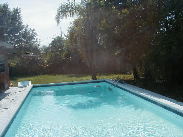
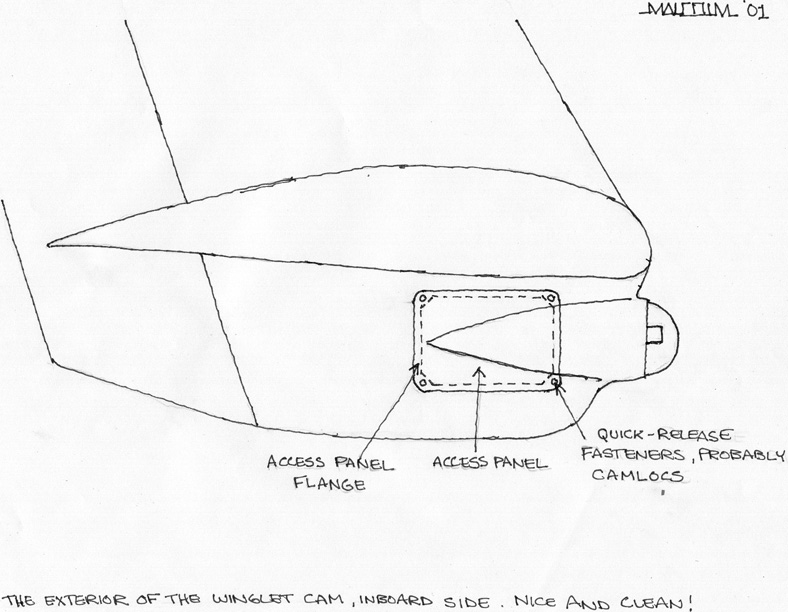
| Photo taken through the dome with a digital camera. The hazy swirl at the upper center of the photo is smoke from Malcolm's grill! | Final diagram: Wingcam Exterior | Final Diagram: Wingcam inner workings. | Detail of Dome Mount Construction. |
|
|
|
|
|
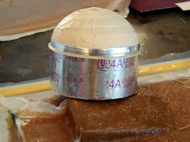
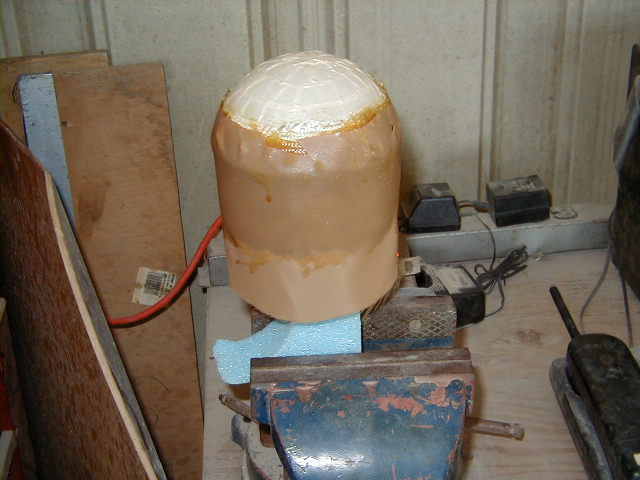
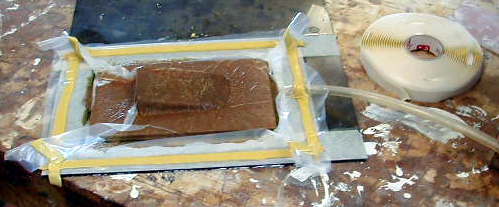
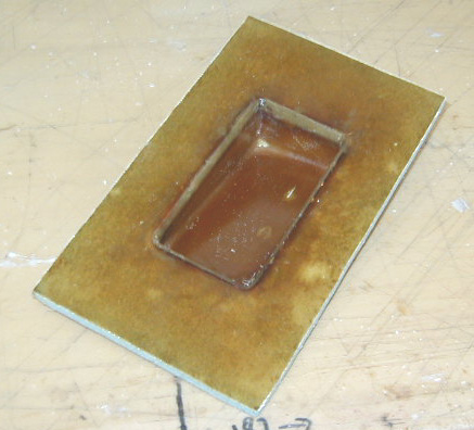
| Detail of mounting rib construction. | Diagram of the wingcam servo mount. The compression springs will allow for further fine adjustment in the angle of the servo and therefore the overall camera field of view. | Dome mount tool, ready for layup. | Dome mount laid up. |
|
|
|
|
|
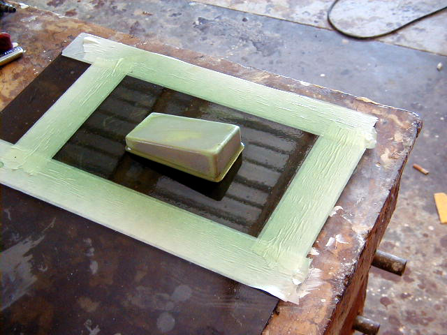
| Tool for creating the rib on which the servo will be attached. Top and inboard view. | Another view of the rib tool, top and outboard. | Rib laid up over tool. Vacuum bagging technique used. | Photo of both aft and forward ribs prior to cutting down in size to fit within the hollow lower winglet. |
|
|
|
|
|
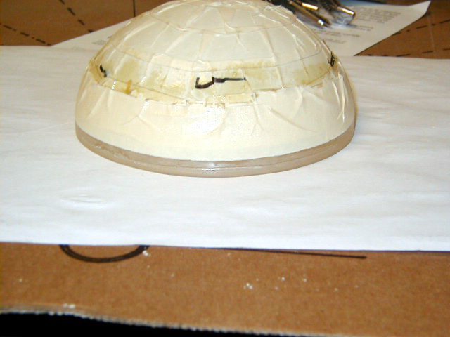
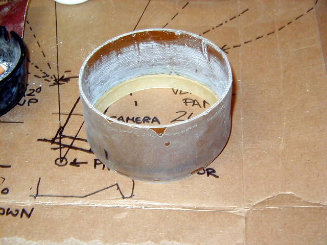
| Aft side of servo mounting rib. | Forward side of completed servo motor mount rib. | Edge of acrylic dome is cleaned up. | Shot of the dome mount cylinder. |
|
|
|
|
|
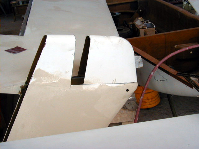
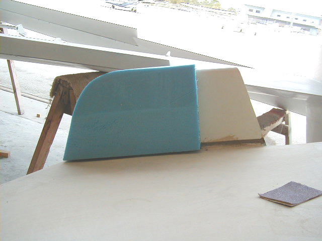
| Tooling wax seen inside dome mount cylinder which will allow placement of an "O" ring. | Dome Mount with inner flange in place. | Dome fitted into mount. | We planned on reshaping the lower winglets to give (at least to me!) a more aesthetically pleasing shape. The lower winglet is not structural and is, in fact, a hollow molded part. This will make it easier to modify. Basically, the leading edge of the lower winglet will be made flush with the leading edge of the wing. Here you see the front of the winglet removed and shifted forward to the position it will ultimately be placed. Because of the installation of the winglet cam, this piece will be reshaped out of foam as shown in the following pictures. |
|
|
|
|
|
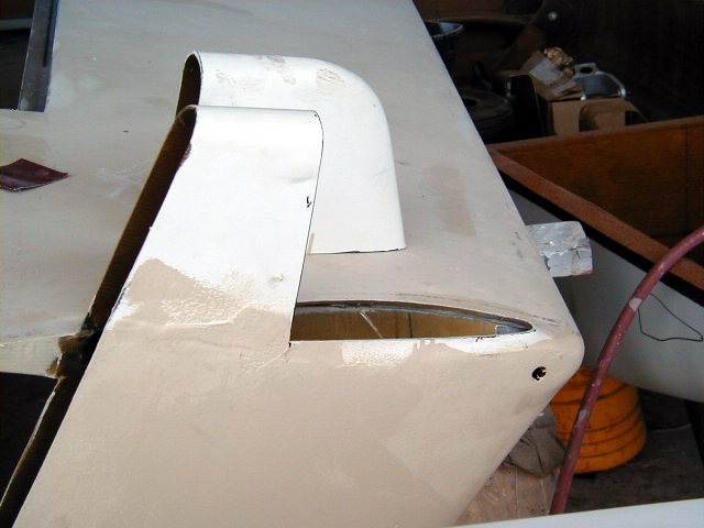
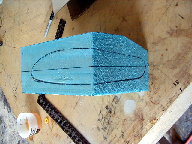
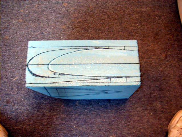
| Old lower winglet piece removed. | The opening to the wire chase conduit running along the leading edge of the wing is seen here through the section from which the lower winglet was removed (arrow). The cables for the cameras will also feed through here. The layup attaching the upper winglet to the wing itself is seen in the center of the photo. | Foam block from which new winglet bottom will be formed. in place. | Another view of the foam block for new winglet. |
|
|
|
|
|
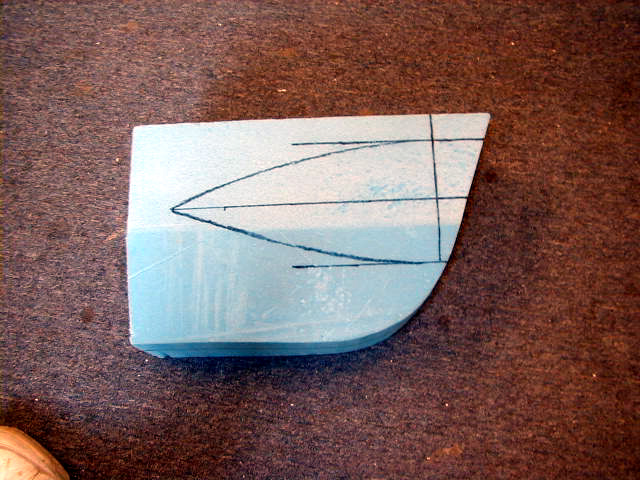
| Footpring of OLD winglet bottom. | Footprint of NEW winglet bottom. | Shape of fairing for the winglet cam seen on the side of the new lower winglet. |
 Comments, questions, and suggestions are welcome! email: rich@rguerra.com
This page visited times.